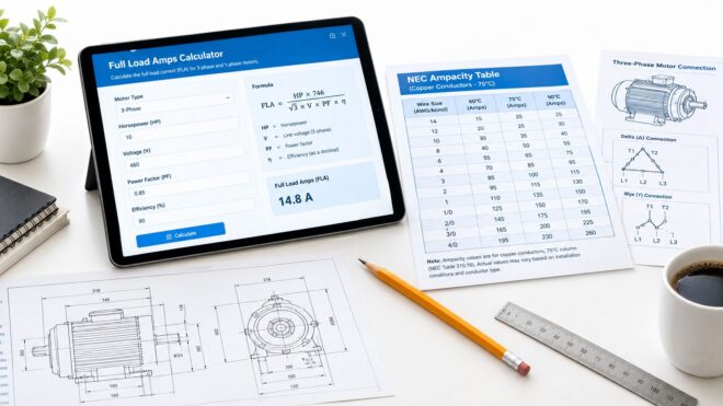
The panel schedule is due, the rooftop fan nameplate is hard to read, and someone has already asked for “the amps” so the breaker and conductors can be carried into the estimate. That request sounds simple, but a commercial estimator often needs two different answers: the current the equipment is likely to draw in operation, and the current value the NEC uses for circuit sizing. A full load amps calculator that gives you only one number can create confusion instead of removing it.
For motor work, start with the equipment nameplate when it's available, then verify the applicable NEC table value before sizing conductors or overcurrent protection. The calculator is useful for estimating operating current, checking assumptions, and building load information. It isn't a substitute for the code tables, manufacturer data, or a complete design review.
What a Full Load Amps Calculator Actually Does
Estimators frequently need an operating amp estimate and a code-based sizing amp from the same motor information. Many online calculators blur those outputs, even though they serve different decisions.
The operating figure is a calculated estimate of steady-state current. It can help with service-load discussions, generator capacity checks, energy analysis, and a sanity check against the motor nameplate. The code-based figure comes from the applicable NEC motor full-load current table. For motor circuits, that table value is the design reference for conductor ampacity, overcurrent protection, and related motor-circuit decisions. The motor calculator reference identifies Tables 430.247, 430.248, and 430.250 as quick-reference sources for motor full-load current.
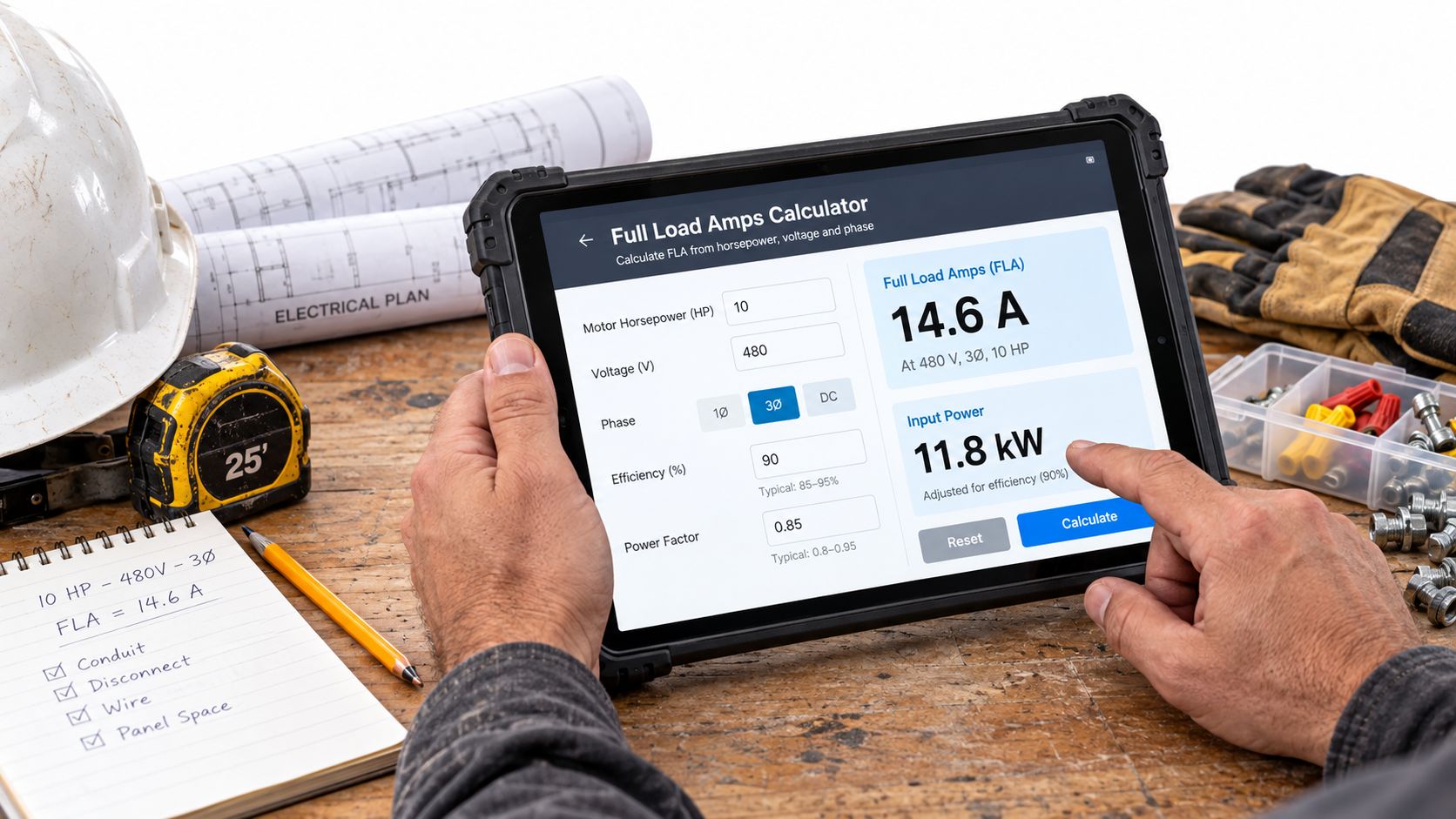
Separate the two outputs
A credible full load amps calculator should show whether its result is:
- Calculated operating current: Derived from horsepower, voltage, phase, efficiency, and power factor. Use it as an estimate of expected running current.
- NEC table current: Looked up from the motor full-load current table for the horsepower, voltage, and phase. Use it for code-based sizing decisions.
- Nameplate current: Taken directly from the manufacturer's data plate. Use it for motor-specific information, especially overload selection, when the equipment documentation provides it.
That distinction belongs in your worksheet, not in a footnote. Put the table value and applicable sizing multiplier into the panel schedule, feeder calculation, or one-line design. Keep the calculated operating estimate available for load modeling and troubleshooting, but label it clearly so nobody mistakes it for the governing design number.
The calculator should also flag when the nameplate value is available. A formula can estimate current from electrical assumptions, but it can't replace the manufacturer's tested operating data or the NEC value selected for circuit sizing.
Key Definitions You Need Before Using Any Calculator
A junior estimator can avoid most FLA mistakes by using the terms consistently. Full-load amps, often written as FLA or FLC in motor work, describes the current associated with a motor operating at its rated output under its specified electrical conditions. In a code calculation, the table-based full-load current becomes the key design reference.
Nameplate FLA is the current printed on the motor data plate. It reflects the manufacturer's motor design and testing, so it may not match a formula result or the NEC table value. Don't erase that distinction from your notes. Record the nameplate value separately from the table lookup.
| Term | Definition | Typical Use |
|---|---|---|
| Full-load amps, FLA or FLC | Current associated with rated motor operation, with the exact design use depending on the source of the value. | Operating estimates and NEC motor sizing workflows. |
| Nameplate FLA | Manufacturer's current rating printed on the motor data plate. | Motor-specific overload and operating checks. |
| Service factor | A motor rating that indicates permitted operation above rated load under defined conditions. | Overload protection and motor evaluation. |
| Efficiency | The share of electrical input converted into useful mechanical output. | Formula-based operating-current estimates. |
| Power factor | The relationship between useful power and reactive current in an AC load. | Formula-based AC current estimates. |
| Voltage | The electrical potential supplied to the motor. | A primary calculator input and field verification point. |
| Phase | The system configuration, commonly single-phase or three-phase for these calculations. | Formula selection and NEC table selection. |
| Horsepower | The motor's rated mechanical output. | Formula input and NEC table lookup input. |
Why the vocabulary matters
Efficiency and power factor both affect a calculated result, but they describe different electrical behavior. Voltage, phase, and horsepower select the calculation path, while the nameplate and NEC table determine which current values should carry design authority.
Service factor deserves separate attention. It can affect overload settings, but it doesn't turn a formula estimate into the NEC sizing value. Keep the operating estimate, nameplate information, and code lookup in separate columns so the next person reviewing the estimate can follow your reasoning.
Single-Phase and Three-Phase FLA Formulas
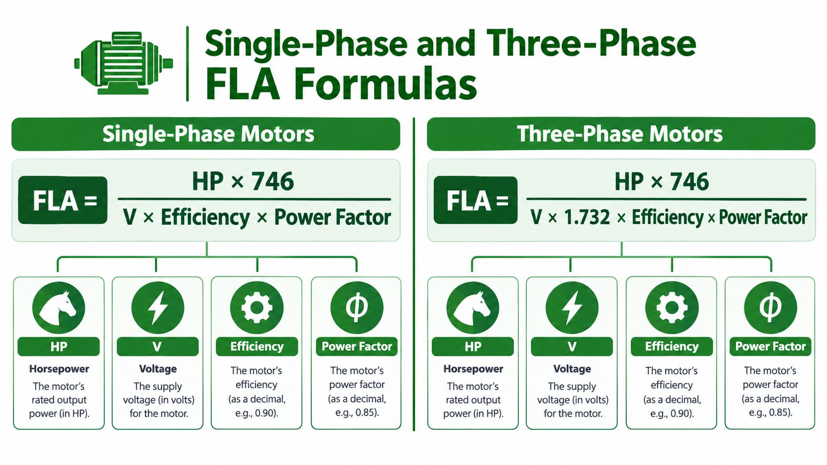
A formula-based FLA estimate starts with the motor's mechanical output and converts it to electrical input. In the equations below, HP is horsepower, V is voltage, efficiency is expressed as a decimal, and power factor is also expressed as a decimal. The constant 746 converts horsepower to watts, while 1.732 represents the square root of three for a three-phase system.
For a single-phase motor:
FLA = (HP × 746) / (V × Efficiency × Power Factor)
For a three-phase motor:
FLA = (HP × 746) / (1.732 × V × Efficiency × Power Factor)
Worked three-phase estimate
Take a 10 HP, 460 V, three-phase motor with 0.88 efficiency and 0.86 power factor.
- Convert the motor output to watts: 10 × 746 = 7,460 watts.
- Multiply the denominator: 1.732 × 460 × 0.88 × 0.86.
- Divide the output by that denominator.
- The result is approximately 12.8 A.
That result is useful as an operating estimate. It can help you test whether a nameplate value appears reasonable or whether a proposed load calculation contains a voltage or phase mistake. For a related explanation of current conversion, see this watts-to-amps calculation guide.
Practical rule: Use the formula when you need an operating estimate or when nameplate information is unavailable. Before sizing motor conductors or protection, check the applicable NEC table.
The formula has limits. It depends on accurate efficiency and power-factor inputs, and those values may vary by motor design and operating condition. The formula result usually isn't the number that governs motor conductor and overcurrent sizing when an NEC table applies.
Why NEC Table Values Govern Motor Sizing
For motor circuits, the NEC table value controls the sizing workflow. A formula-based result can be reasonable for estimating running current, but a designer typically uses the standardized full-load current value assigned to the motor's horsepower, voltage, and phase.
The primary references are:
- Table 430.247: Direct-current motor full-load currents.
- Table 430.248: Single-phase AC motor full-load currents.
- Table 430.250: Three-phase AC motor full-load currents.
The motor reference card linked earlier identifies these tables as quick-reference sources. The important estimating habit is to label a formula result as calculated operating current and the table result as NEC sizing current.
Why the table matters
Standardized table values give contractors, engineers, and inspectors a common design basis. If a drawing uses a formula result where the applicable NEC table calls for a different full-load current, a plan reviewer may question the conductor ampacity, branch-circuit protection, or overload coordination. That's why commercial electrical code compliance depends on more than entering horsepower and voltage into a calculator.
For a motor branch circuit, the conductor calculation commonly begins with 125% of the applicable table full-load current, subject to the complete requirements of the adopted code and the specific installation. Short-circuit and ground-fault protection also follows motor-circuit rules, including the provisions associated with NEC 430.52. The table value therefore feeds several downstream decisions, while the formula estimate mainly helps describe expected operation.
Use the calculator as a front end, not the authority
A good workflow looks like this:
- Read the nameplate and record its FLA, horsepower, voltage, phase, service factor, and other relevant data.
- Calculate an operating estimate if you need to check the data.
- Look up the NEC table full-load current.
- Apply the motor conductor and protection rules that govern the installation.
- Document which value was used for each decision.
The result should never be a single unlabeled amp number. It should show the source and purpose of every current value.
Worked Example for a Commercial Motor Circuit
Consider a 25 HP, 460 V, three-phase Design B induction motor serving a rooftop supply fan. The first question isn't what a generic formula produces. It's which NEC table value applies.
Start with the table value
Use NEC Table 430.250 for the three-phase motor and record the table full-load current as 34 A, as specified in the project example. That is the value used for the motor-circuit sizing path.
For the branch-circuit conductors, apply the required 125% starting point:
34 A × 1.25 = 42.5 A
The conductor must have ampacity at least equal to the resulting design value, subject to the applicable temperature, termination, adjustment, and correction requirements. For this example, the selected design lands on 6 AWG copper, with a 50 A breaker carried into the branch-circuit design. Verify the actual conductor ampacity and termination conditions against NEC 110.14(C) and Table 310.16 for the installation rather than treating the example as a universal selection.
Coordinate protection and overloads
Short-circuit and ground-fault protection follows the motor rules, not the operating estimate. Applying the example's 250% of FLC starting point gives:
34 A × 2.5 = 85 A
The next standard inverse-time breaker selection in this example is 90 A, subject to the permitted adjustments and the specific equipment listing.
Overload protection uses a different decision path. For a motor with a 1.15 service factor, the example checks overload selection near 115% of nameplate FLA. For a motor with a 1.0 service factor, the example uses 125% instead. The nameplate value matters here because overload protection is tied to the motor's marked characteristics, not just the table lookup.
Keep the operating estimate separate
A formula-based operating estimate of about 27 A at typical load can be useful for evaluating expected running current. It does not replace the 34 A NEC sizing value for the conductor and motor protection workflow.
| Decision | Current source | Example value |
|---|---|---|
| Expected operating current | Formula-based estimate | About 27 A |
| Motor sizing reference | NEC Table 430.250 | 34 A |
| Branch-conductor starting point | 125% of table FLC | 42.5 A |
| Example conductor and breaker selection | Installation review required | 6 AWG copper and 50 A breaker |
| Example short-circuit protection selection | 250% starting point, then standard size | 90 A inverse-time breaker |
The lesson is simple. Don't carry the operating estimate into the breaker column just because it looks lower. Put each value beside the decision it supports.
Choosing the Right Calculator for Motor, Equipment, and EV Loads
A motor calculator isn't automatically the right tool for every commercial load. The equipment type determines the inputs, the governing NEC article, and whether a table lookup or nameplate value has priority.
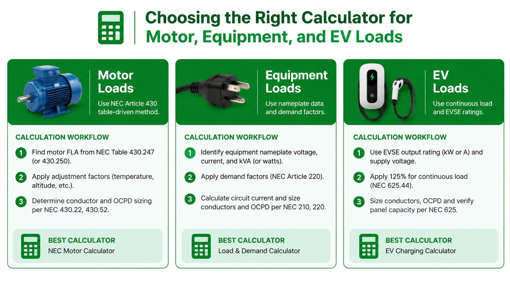
| Load type | Best starting input | Design path | Calculator limitation |
|---|---|---|---|
| Motor | Horsepower, voltage, phase, nameplate data | NEC Article 430, including the applicable motor table and multiplier rules | A formula-only tool provides an operating estimate, not the complete sizing answer. |
| General commercial equipment | Nameplate amps, watts, voltage, and phase | Equipment requirements plus applicable load-calculation rules | Horsepower assumptions can misrepresent HVAC, kitchen, and control equipment. |
| EV charging | Charger nameplate data, input voltage, phase, and equipment configuration | NEC Article 625 and applicable continuous-load requirements | A motor-only calculator may ignore charger-specific behavior and manufacturer requirements. |
Match the tool to the load
A motor calculator works well when you need to compare a nameplate value with a calculated estimate or prepare a table lookup. It doesn't work well as the sole method for resistance heating, kitchen equipment, packaged HVAC equipment, or electronic controls. Those loads should start with their nameplate information and the rules that apply to their equipment category.
EV charging deserves its own workflow. Commercial chargers can include power electronics that make efficiency and operating behavior different from a simple motor. DC fast-charging equipment also requires attention to rectifier efficiency and the manufacturer's input data. The calculator should tell you what assumptions it used, not hide them behind one output field.
Mixed commercial loads make this distinction more important. A property may have motors, EV chargers, lighting controls, and equipment with different power factors on the same service. Use a load-by-load worksheet, preserve the nameplate source, and identify whether each current is an operating estimate, a code table value, or a manufacturer rating.
Applying Continuous-Load and Conductor Sizing Rules
Once the correct FLA or FLC is identified, the next step is turning it into a circuit design. A load expected to operate at maximum current for three hours or more is treated as a continuous load for the applicable calculation, and NEC 210.20(A) requires sizing at 125% of the continuous load. That is equivalent to using only 80% of conductor ampacity for that portion of the circuit, as summarized in the commercial panel upgrade reference.
| Application | NEC Reference | Multiplier | Resulting Design Value |
|---|---|---|---|
| Continuous-load overcurrent calculation | NEC 210.20(A) | 125% | Continuous load × 1.25 |
| Motor branch-circuit conductor starting point | NEC motor rules | 125% | Table motor FLC × 1.25 |
| Continuous portion of conductor or breaker capacity | Continuous-load principle | 80% usable capacity | Load must fit within 80% of the relevant rating |
Don't confuse the two uses of 125%
For a general continuous load, the 125% rule protects the circuit from being treated as if it can operate indefinitely at the full device rating. For a motor branch circuit, the conductor calculation uses the motor's table full-load current and the applicable motor-conductor rule. The numbers may look similar, but the governing articles and equipment context are different.
The conductor reference for this step is NEC Table 310.16. That table is defined for conductors in raceway, cable, or earth at 30°C ambient with not more than three current-carrying conductors, and it provides separate 60°C, 75°C, and 90°C columns for copper and aluminum conductors. Actual installation conditions can require adjustment or correction.
Continue the calculation
Using the separate example provided, a motor with 30 A FLC produces:
30 A × 1.25 = 38 A
The conductor must meet at least 38 A under the applicable conditions. The example then rounds to a 6 AWG copper conductor from Table 310.16 and selects a 40 A inverse-time breaker, subject to verification of termination ratings, conductor insulation, installation conditions, and the complete motor-protection rules.
The calculator's job ends when it gives you a correctly labeled current. The estimator's job begins when that value is applied to the right article, table, conductor condition, and protection requirement.
Common Mistakes That Skew FLA Results
Most bad FLA results don't come from difficult mathematics. They come from entering the wrong input or assigning the result to the wrong design decision.
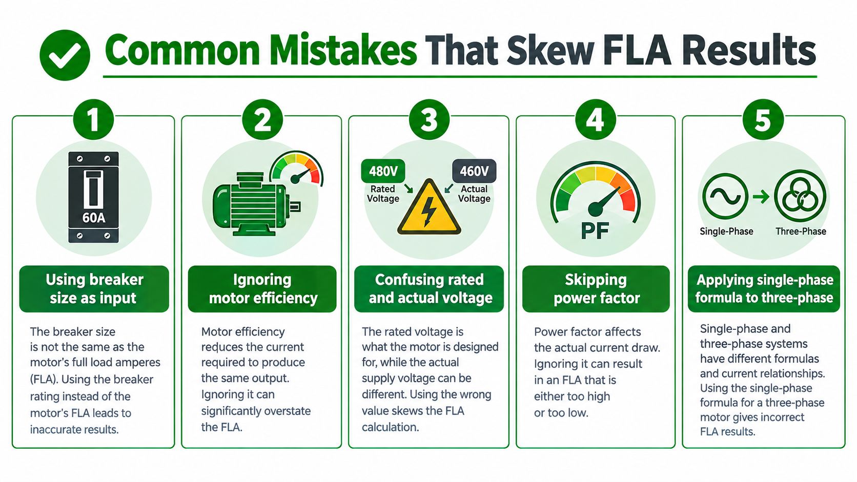
The errors that show up repeatedly
- Using breaker size as the load input: A breaker protects the circuit. It doesn't tell you the motor's actual operating current. Back-solving from breaker size defeats the purpose of the calculation.
- Confusing nameplate FLA with NEC FLC: The nameplate is manufacturer-specific. The NEC table value is a standardized sizing reference. Record both instead of choosing one without labeling its source.
- Skipping service-factor information: Service factor can affect overload selection and motor evaluation. Leaving it blank can lead to the wrong protection assumption.
- Mixing voltage configurations: A 208 V system, a 230 V motor connection, and a 460 V supply aren't interchangeable inputs. Confirm the actual line voltage and motor connection before calculating.
- Treating the formula as the code answer: A calculated three-phase result may look precise, but the applicable NEC table governs motor sizing when the table applies.
Efficiency and power factor create another trap. Calculator defaults may not represent the motor on a retrofit project, especially when the replacement motor uses a different efficiency class or electronic drive. If the nameplate gives you tested current, don't replace it with a convenient default.
Field checklist: Confirm the nameplate, voltage, phase, horsepower, efficiency, power factor, and service factor. Then perform the NEC table lookup before selecting conductors or overcurrent protection.
Field Troubleshooting and Sanity Checks
A calculator result should survive comparison with the equipment in front of you. Start with the motor nameplate, then compare that information with a clamp-meter reading taken at the line side of the disconnect while the motor is operating under a normal loaded condition.
Use this sequence:
- Read the data plate: Confirm voltage, phase, horsepower, nameplate FLA, service factor, and connection details.
- Check the supply: Verify the measured voltage and whether the motor is connected as intended, including wye or delta configuration where applicable.
- Measure each line: Compare line currents rather than relying on a single phase reading.
- Investigate high current: Voltage imbalance, harmonic distortion, excessive mechanical load, or a binding fan can raise current.
- Investigate low current: Light loading or a capacitor problem on a single-phase motor can produce a lower reading than expected.
- Recheck assumptions: Confirm efficiency, power factor, and the selected motor class before rerunning the estimate.
The nameplate and NEC table won't always match exactly because they serve different purposes. A meaningful discrepancy deserves manual review, especially when the calculated result, table value, and field measurement point in different directions. Don't change protection based on a clamp reading alone. Treat the measurement as diagnostic evidence and verify the complete motor circuit.
Quick Reference Card for Estimators
Keep this summary beside the takeoff sheet. The central rule is the two-answer method: calculate or measure the expected operating current, then identify the NEC sizing current separately.
| Item | Formula or Rule | NEC Reference | Notes |
|---|---|---|---|
| Single-phase estimate | FLA = (HP × 746) / (V × efficiency × power factor) | Formula estimate | Use when nameplate data is unavailable or an operating estimate is needed. |
| Three-phase estimate | FLA = (HP × 746) / (1.732 × V × efficiency × power factor) | Formula estimate | The result is not automatically the motor sizing value. |
| DC motor table | Look up motor full-load current | NEC Table 430.247 | Use the table value for the applicable DC motor. |
| Single-phase motor table | Look up motor full-load current | NEC Table 430.248 | Use the table value for motor sizing. |
| Three-phase motor table | Look up motor full-load current | NEC Table 430.250 | Use the table value for motor sizing. |
| Continuous-load calculation | Continuous load × 125% | NEC 210.20(A) | Apply the rule to the applicable circuit and equipment. |
| Conductor reference | Verify ampacity under installation conditions | NEC Table 310.16 | Check temperature, conductor count, raceway, cable, earth, and termination conditions. |
| Motor branch conductor starting point | Table FLC × 125% | Applicable NEC motor rules | Do not substitute a generic formula result. |
| Operating-current answer | Formula, nameplate, or measured value | Equipment data and field verification | Useful for expected operation and troubleshooting. |
| Sizing-current answer | NEC table value plus applicable rules | NEC motor articles | Use for conductors, protection, and documented design decisions. |
For a quick voltage sanity check, calculate the expected current for 1 HP, 5 HP, 10 HP, and 25 HP at the actual system voltage, then compare the estimate with the nameplate and the relevant NEC table. Don't treat those horsepower checks as design values. They're input-error screens that can catch a wrong phase selection, an incorrect voltage, or a misplaced efficiency decimal before the number reaches a submittal.
The most reliable worksheet has three clearly labeled columns: operating estimate, nameplate data, and NEC sizing value. If a reviewer can see where each number came from, the FLA calculation becomes a traceable design step instead of an unexplained calculator output.
Access Electrical and Lighting provides commercial electrical troubleshooting, distribution work, panel upgrades, EV charging installation, testing, and maintenance for properties across Southern California. Visit Access Electrical and Lighting to discuss motor-circuit verification, electrical load reviews, and code-aware upgrades with a commercial electrical contractor.