
A facility manager is checking whether a new commercial circuit can carry a lighting retrofit. The fixture schedule lists watts, the panel schedule lists voltage, and the breaker is rated in amps. The calculation looks simple until the load uses alternating current, operates across three phases, or has a power factor below unity.
That's why how to work out watts to amps depends on more than dividing watts by volts. The right calculation starts by identifying the system type, voltage, phase arrangement, and power factor. For commercial lighting, EV charging, motors, and backup equipment, those details determine whether the result is useful or misleading.
Why the Watts to Amps Shortcut Breaks Down on Commercial Jobs
The shortcut amps = watts ÷ volts works as a baseline for a simple DC load or a near-resistive device. It doesn't describe every commercial circuit. A facility estimator who applies it to an AC distribution system may get a current value that ignores power factor and phase relationships.
Consider a 208V three-phase lighting installation with 750W LED high-bay fixtures. Dividing the total real power by 208V can produce a deceptively low answer because the calculation treats the load as though every watt becomes current with a power factor of 1.0. Commercial LED drivers, ballasts, switch-mode power supplies, compressors, and motors don't necessarily behave that way.
The watts-to-amps calculator reference shows the distinction between the basic DC relationship, the single-phase AC formula, and the three-phase formula. For single-phase AC, the relationship is amps = watts ÷ (volts × PF). For a balanced three-phase load, the denominator also includes √3.
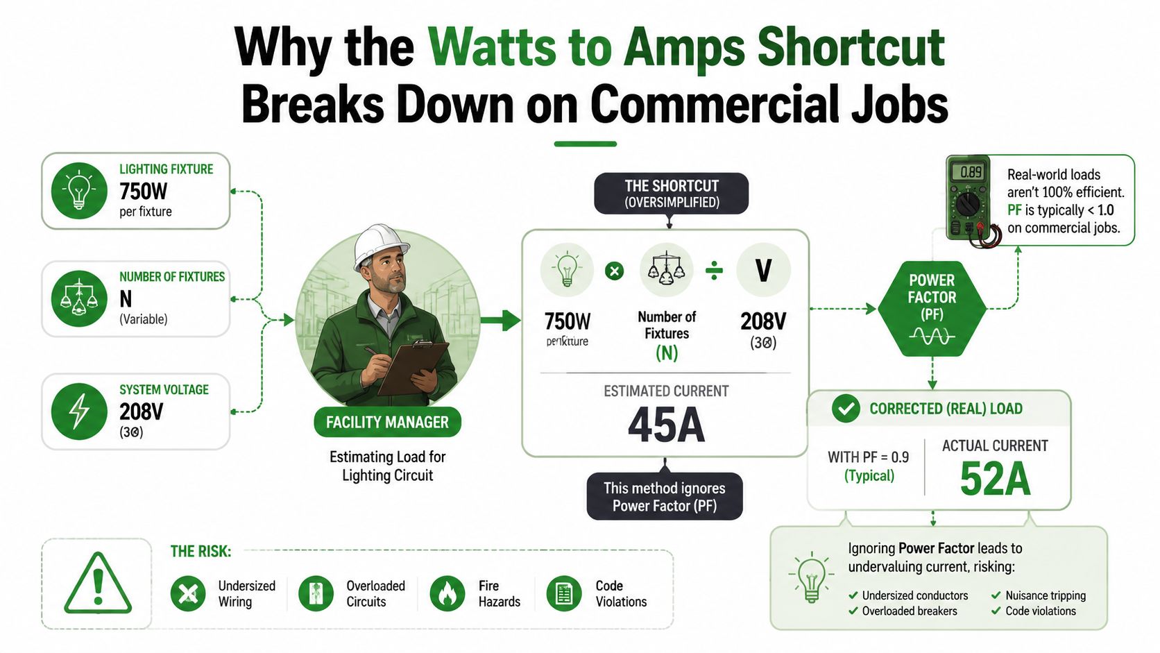
What the shortcut leaves out
A commercial current calculation may require all of these inputs:
- System type: DC, single-phase AC, or three-phase AC.
- Voltage selection: Line-to-neutral or line-to-line, depending on how the load connects.
- Real power: The watts the equipment uses to perform work.
- Power factor: The relationship between real power and apparent power in an AC load.
- Operating behavior: Running current, inrush, charging changes, and nonlinear current waveforms.
Lower power factor means the equipment draws more current for the same real power. That additional current affects conductor sizing, heat, breaker loading, voltage drop, generator capacity, and inverter planning. A facility team that skips those inputs may oversize conductors, undersize overcurrent protection, or discover the problem only during commissioning.
Voltage drop can create another problem even when the arithmetic is correct. Long feeder runs, heavily loaded conductors, and motor or lighting circuits can require a separate voltage drop assessment before the installation is finalized.
Field rule: Write the system voltage, phase, and assumed PF on the work order before dividing watts by volts.
The Core Formulas for DC and Single-Phase AC Loads
Start with DC because it provides the cleanest version of the relationship:
I = P ÷ V
In this formula, I is current in amps, P is real power in watts, and V is voltage in volts. If a DC device uses 600W at 120V, the calculation is:
I = 600W ÷ 120V = 5A
Power factor doesn't appear in this equation because the basic DC relationship doesn't use AC phase displacement. The result is still based on the actual operating voltage and power rating, so verify both rather than relying on a nominal system label.
Single-phase AC with power factor
For single-phase AC equipment, use:
I = P ÷ (V × PF)
A 1,500W load at 120V with a PF of 0.8 works out as:
I = 1,500W ÷ (120V × 0.8)
I = 1,500 ÷ 96
I = 15.625A
Rounded for practical planning, that's about 15.6A. The basic shortcut would produce 12.5A, so it understates the current when PF is below 1.0. The difference matters when a breaker, conductor, generator, inverter, or panel section is close to its available capacity.
Use line-to-neutral voltage when the equipment is connected from one phase to the neutral. Use line-to-line voltage when the equipment is connected between two ungrounded conductors. The voltage printed on the equipment nameplate and the actual connection diagram should control the choice.
A resistive heater may be close to unity power factor, but commercial electronic loads vary. LED drivers with active power factor correction may operate near 0.9 to 0.99, while older magnetic ballasts may sit closer to 0.5 to 0.7, as summarized in the power-factor-aware watts and VA guide. Use the manufacturer's data or a meter when available.
DC versus single-phase AC current
The table below compares the same real-power loads under different assumptions. The AC columns include a PF of 0.9.
| Load | 120V DC | 120V AC PF 0.9 | 240V AC PF 0.9 |
|---|---|---|---|
| 600W | 5A | 5.56A | 2.78A |
| 1,000W | 8.33A | 9.26A | 4.63A |
| 1,500W | 12.5A | 13.89A | 6.94A |
The table shows why increasing voltage reduces current for the same real power, while a lower PF increases AC current. Three-phase systems add another term, √3, because the phases share the total load.
Three-Phase Formulas and Worked Commercial Examples
For a balanced three-phase load, use:
I = P ÷ (√3 × Vᴸ × PF)
Here, P is total real power in watts, Vᴸ is line-to-line voltage, and PF is power factor. The square root of three, written as √3, is approximately 1.732.
Example one, 480V lighting
A commercial lighting circuit supplies ten 400W LED high-bay fixtures at 480V three-phase with a PF of 0.95.
First calculate the total real power:
10 fixtures × 400W = 4,000W
Then substitute each value:
I = 4,000W ÷ (1.732 × 480V × 0.95)
I = 4,000 ÷ 790.224
I ≈ 5.06A per phase
The result is roughly 5.06A per phase under the stated operating assumptions. Breaker selection still requires a complete code review, including continuous load treatment, conductor ampacity, equipment ratings, fault-current requirements, and the manufacturer's instructions. The conversion alone doesn't authorize a particular breaker.
Example two, three-phase EV charging
A Level 2 EV charger is rated at 11.5kW on a 208V three-phase service with a PF of 0.98.
Convert kilowatts to watts first:
11.5kW × 1,000 = 11,500W
Now calculate:
I = 11,500W ÷ (1.732 × 208V × 0.98)
I = 11,500 ÷ 352.86
I ≈ 32.6A
Using rounded intermediate values can produce a result near 32.8A, but the exact displayed answer depends on rounding. That operating current points toward a 40A overcurrent device in the example, while conductor selection must follow the applicable code, terminal ratings, equipment instructions, installation conditions, and local requirements. A design reference such as commercial transformer sizing guidance can also help when the new load affects upstream distribution.
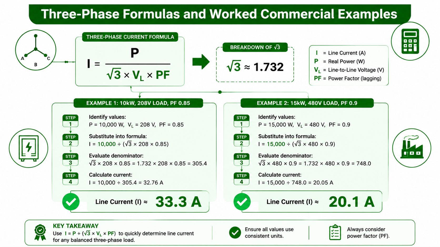
Choosing the voltage correctly
The formula uses line-to-line voltage for a balanced three-phase load. A 240V delta system and a 120/240V high-leg delta system need careful conductor identification before anyone selects the voltage value. The same three-phase relationship can apply to motors, HVAC equipment, and EVSE, but only after the equipment connection, line voltage, total watts, and PF are confirmed.
Estimator's check: If the nameplate gives kVA rather than watts, don't force the value into a watts formula without understanding the equipment's rating and power factor.
Applying the 125% Continuous Load Rule to Your Sizing
The current conversion gives you the operating current. It doesn't finish the circuit design when the load is expected to run continuously. Under NEC 210.20(A) and 215.3, a load expected to operate for three hours or more is treated as continuous, and the continuous portion is calculated at 125% for sizing the circuit and overcurrent protection.
The multiplier is straightforward:
Minimum calculated ampacity = operating current × 1.25
For a circuit drawing 8.7A continuously:
8.7A × 1.25 = 10.875A
That result is higher than the unadjusted running current. The designer then selects conductors and overcurrent protection using the applicable ampacity tables, terminal temperature ratings, adjustment factors, equipment limitations, and standard device sizes. A breaker isn't selected by rounding the running current to the nearest available number.
Parking-lot lighting example
Suppose a parking-lot retrofit uses 240W fixtures on a 277V single-phase circuit. Assuming unity power factor for this simplified illustration:
240W ÷ 277V ≈ 0.87A per fixture
For ten fixtures:
0.87A × 10 = 8.7A
Applying the continuous-load multiplier:
8.7A × 1.25 = 10.875A
That calculation means a 10A breaker would not provide the required margin for the continuous calculation. The next standard breaker size in the example is 15A, but the final selection still depends on the complete installation and applicable code provisions.
Practical rule: Apply the continuous multiplier before choosing the breaker, then verify that the conductor ampacity supports the selected protection.
A commercial electrical panel upgrade assessment may be necessary when a retrofit adds load to a panel with limited spare capacity. The panelboard schedule, feeder rating, existing demand, and available fault current all matter. The watts-to-amps result is one input, not the entire load calculation.
Measuring Real Current and Avoiding Common Field Mistakes
Nameplate watts and an assumed PF are design inputs until a meter confirms what the equipment draws in operation. A clamp meter placed around one ungrounded conductor can show running current, while a power meter can provide a more complete view of watts, voltage, PF, and waveform behavior.
A calculated value and a field value won't always match. A clamp reading on a 208V three-phase LED driver panel may come in below the design estimate when the assumed PF was conservative, or above it when the driver behavior, voltage, loading, or assumptions differ. That discrepancy is useful because it tells the electrician to investigate instead of quietly changing the panel schedule.
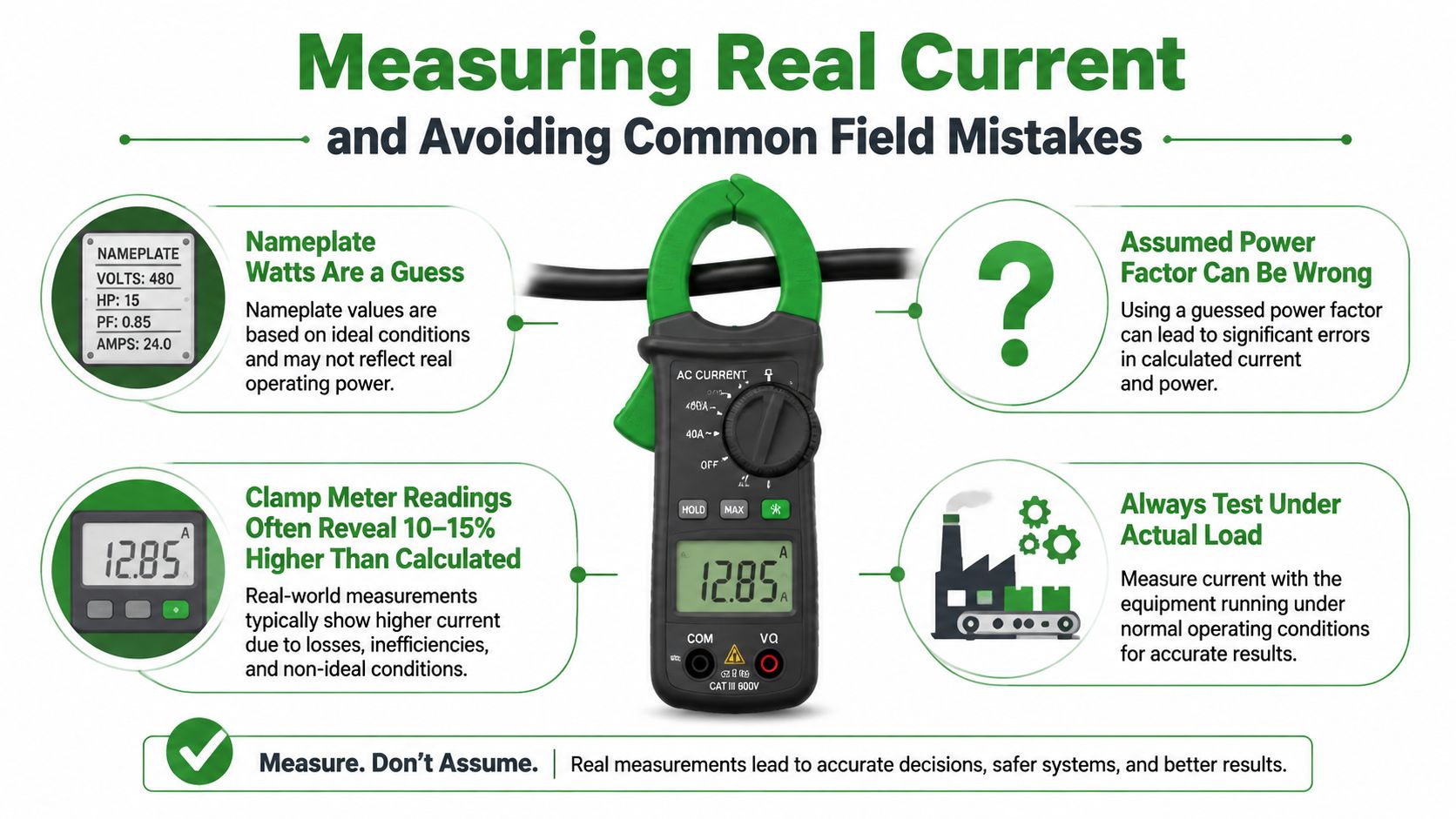
What to verify in the field
- Measure under actual load: Test while the lighting, HVAC, EV charging, or backup equipment is operating in its normal mode.
- Check all phases: A single phase reading won't reveal imbalance across a three-phase panel.
- Capture operating changes: EV chargers and other electronic equipment may change input current as their operating state changes.
- Inspect the neutral: Office equipment and other nonlinear loads can place harmonic current on the neutral even when phase readings look reasonable.
- Compare voltage at the equipment: A panel reading taken under light load may not represent the voltage available at the far end of a loaded feeder.
- Look for inrush: LED drivers, chargers, motors, and switch-mode power supplies can draw a short starting current that a running calculation doesn't show.
A clamp meter alone may not measure PF or harmonics. For a difficult commissioning issue, use a suitable wattmeter or power-quality analyzer and follow the instrument manufacturer's safety category and operating instructions.
Log before signing off
A panel schedule should reflect measured conditions when the installation is available for testing. Log current on each phase through a representative duty cycle, note the voltage at the equipment, record the operating state, and document any unusual startup behavior.
Commissioning habit: Don't sign off on a commercial load from a nameplate alone when a properly rated meter can verify the installation.
The PF and VA explanation for mixed AC loads is useful when a wattage figure doesn't explain the apparent power required by the system. That distinction becomes especially important for LED retrofits, EV infrastructure, and backup power systems.
Safety Habits and Quick Calculator Tools to Lock It In
A calculator is valuable for checking arithmetic. It can't identify a misread line voltage, an overloaded neutral, an undersized feeder, a loose termination, an incorrect conductor rating, or a breaker that doesn't match the equipment. Treat online tools as a second set of arithmetic eyes, not as approval for an installation.
Use this checklist before issuing a quote, changing a panel schedule, or energizing a new commercial load:
- Identify the system: Record DC, single-phase AC, or three-phase AC, along with the actual operating voltage.
- Select the correct voltage: Mark whether the formula uses line-to-neutral or line-to-line voltage.
- Record power factor: Use the nameplate value when available, and identify where field measurement is required.
- Convert units: Change kW to W before inserting the value into the formula.
- Apply continuous-load treatment: Check whether the equipment's operating schedule requires the applicable multiplier.
- Review conductor conditions: Confirm conductor ampacity, temperature ratings, termination ratings, adjustment factors, and installation conditions.
- Check protection: Verify the breaker or fuse against the calculated load, equipment listing, and governing code.
- Measure in service: Use a properly rated clamp meter or power analyzer under the operating condition.
- Document findings: Put readings, assumptions, phase values, and equipment status in the work order.
Use calculators as a cross-check
A basic watts-to-amps tool can confirm DC and simple single-phase arithmetic. A PF-aware three-phase calculator is more useful for commercial equipment because it keeps √3 and power factor visible in the calculation. The RapidTables electrical calculator provides formulas for these common configurations, while the Access Electrical and Lighting foot candle calculator can help connect a lighting layout to fixture quantity, rated input, and connected load.
The most reliable habit is simple: write voltage, phase, and PF before doing the division. That one line prevents the common mistake of applying a DC shortcut to a three-phase commercial load.
For Southern California facilities that need more than a calculation, Access Electrical and Lighting provides commercial lighting and electrical services, including LED retrofits, EV charging installation, panel work, testing, and documented infrared inspections. Visit Access Electrical and Lighting to discuss a load assessment, retrofit, or troubleshooting project with a commercial electrical contractor.