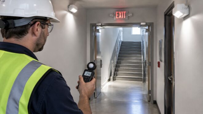
You're standing in a corridor after the lights drop. The legend over the stair door is still glowing, but the stretch of hallway between you and that door has gone dark. You can name the exit. You can't see the floor you have to cross to reach it.
That gap is what an emergency exit sign with remote head is built to close. The sign marks the door. The heads light the path. Treat the whole assembly as one life-safety circuit. Coverage, load, and the test record for every head get judged together, not as a sign that happens to have extra lamps bolted on.
How a Remote-Head Exit Sign Works
Say smoke starts to fill a corridor. The exit sign above the stairwell door is still lit, but the hallway between the two exits is dark. People can see the doorway. They can't see the turn, the step, or the person in front of them.
Think of the sign face as a signpost. It marks the door. The remote heads act like floodlights aimed along the path that leads to that door. Light on the legend is not light on the walking surface.
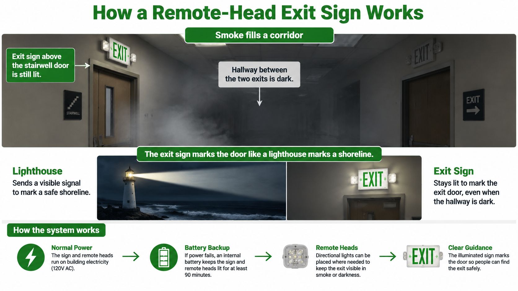
The circuit has three parts, in a fixed order.
Sign face. The face carries the word Exit so the doorway reads as an exit from the approach aisle.
Remote heads. One or more heads mount along the route, not only beside the sign, and throw light down the corridor, the stair, or the open floor.
Power source. An integral battery inside the unit, or a central emergency unit, feeds those heads through conductors. Battery backup for emergency exit lights is what keeps that circuit alive after normal power drops. If the battery, the conductors, or the load don't match, a head that looked fine at install goes dim when you need it.
Workplace rules require every exit route to be lighted so employees with normal vision can see along it. Light has to reach the extended path, not only the doorway the sign hangs over.
Two setups side by side
| Feature | Integral-only sign | Remote-head system |
|---|---|---|
| Light source | Lamps built into the sign face | Sign face plus one or more remote heads |
| Coverage | Sign face and a small area around it | Corridors, stairs, aisles and open areas along the route |
| Power | Integral battery inside the sign | Integral or central power unit feeding remote heads |
| Failure exposure | One unit fails, one point is lost | A head or load fault can remove light from a section of the route |
| Testing scope | Sign and its battery | Every remote head plus total runtime |
| Typical use | Doorways in small rooms | Large, open or visually obstructed floor plans |
A lit legend over a door does not light the hallway that leads to it.
Three questions decide which row of that table your floor belongs in.
How long is the egress path? A short run beside a small room can live on the sign's own lamps. A long corridor cannot.
Does the path turn or climb stairs? Each change of direction is a spot where someone loses the route if that spot stays dark.
Do partitions, shelving, or columns block the view? If the sign stays hidden until the last few steps, heads have to light the obstructed stretch.
Remote Head Models, Outputs and Mounting Options
Four ratings decide whether a head belongs on your circuit. Skip one and the rest of the paperwork won't save the install.
Rated voltage has to match the power unit. A head built for a specific low-voltage output is not a generic lamp you can hang on any supply.
Fixture wattage adds to the emergency load of the whole system. Total every head before you order another one.
Lumen output sets how far the beam reaches. A longer or wider path needs more output, not a second copy of a small head.
Housing has to suit the wall, ceiling, or damp location where the head will sit.
Two published Lithonia listings
In 2025, Acuity Brands listed Lithonia Lighting ELA Q remote heads at 9.6 VDC, with fixture wattages from 5 W to 20 W. The same maker's ERE emergency remote heads are listed at 45, 76, 85, and 150 lumens. A rating that isn't on the listing stays unknown until you open the data sheet.
| Model | Rated voltage | Output | Best fit |
|---|---|---|---|
| Lithonia ELA Q thermoplastic remote head | 9.6 VDC | 5 W to 20 W fixture wattage | Battery-fed corridors and stair runs |
| Lithonia ERE emergency remote head | Not published, confirm on the data sheet | 45, 76, 85 and 150 lumens | Spaces where output must match path length |
The ELA Q line is the one you can size by watts against a 9.6 VDC unit. The ERE line is the one you pick by lumens when path length is the question. Neither listing replaces the other, and a missing voltage on the ERE row is a reason to stop, not a reason to guess.
Pick a head in this order.
- Confirm the voltage match against the power unit nameplate, not against a similar-looking head already on the wall.
- Add each head's wattage to the load sheet before you commit to the count.
- Pick the output for the path length, using the higher lumen steps where the throw is long.
- Select the housing for the actual mount, including moisture if the head sits near an exterior door.
Check the model number against the manufacturer data sheet before the order goes out. A head that arrives at the wrong voltage won't charge correctly, and it won't pass a discharge test later.
Code Requirements for Exit Sign Visibility
An inspector is not finished when they see a sign on the wall. OSHA's 29 CFR 1910.37 requires every exit route to be adequately lighted so employees with normal vision can see along it, and it requires each exit to be clearly visible and marked with an "Exit" sign. Where the direction of travel is not immediately apparent, additional signs must identify the route to the nearest exit or exit discharge.
The same rule sets numbers you can measure. An exit sign must receive at least 5 foot-candles (54 lux) from a reliable light source and must use a distinctive color. The word "Exit" must be plainly legible, with letters at least 6 inches (15.2 centimeters) high, and the principal letter strokes at least three-fourths of an inch (1.9 centimeters) wide.
Thresholds that remote heads have to support
| Requirement | Threshold | Why it matters for remote heads |
|---|---|---|
| Illumination on the sign face | At least 5 foot-candles (54 lux) from a reliable light source | Heads must not be shaded or dimmed by distance |
| Height of the word Exit | At least 6 inches (15.2 cm) | Letters must be readable from the approach aisle |
| Width of principal strokes | At least three-fourths of an inch (1.9 cm) | Strokes must hold their shape at viewing distance |
| Color | A distinctive color | Sign must stand out from surrounding finishes |
| Direction signs | Required where travel direction is not immediately apparent | Route signs must point to the nearest exit |
| Route lighting | Adequate light for employees with normal vision to see along the route | Remote heads must cover corridors, stairs and open areas |
Remote heads are how you cover corridors and stairs the sign's own lamps never reach. They don't shrink the letter. They don't repaint the legend. They put light on the parts of the route a person still has to walk.
Practical rule: If you can't read the legend and see the next step from the same standing point, the circuit isn't finished.
Run three checks on a normal walk-through. Hold a light meter on the sign face and compare the reading with the illumination threshold. Measure letter height and principal stroke width with a tape. Then walk the route and note every stretch that goes dark between heads.
Exit signage mounting height sits alongside those checks, because a compliant legend still fails if people can't see it from the approach. Local amendments and the building's occupancy can add more rules, so confirm the set with the authority having jurisdiction before you call the job done. Write each measurement down and mark every gap for correction. A verbal "it looked fine" won't answer an inspector who asks for the number.
Where Remote Heads Belong Along an Egress Path
Place heads along the walking path, not along the ceiling grid. A neat row of fixtures can still leave the turn dark.
Stand at the exit door and look back into the building. At each decision point, consider what a person would see. Heads belong at corridor changes, at the top and bottom of stair runs, near doors that lead into the route, and in open areas where the path is hard to follow. Shelving, partitions, and columns cut the beam, so check the sightline from each head to the next head and on to the exit.

Long conductor runs drop voltage. The far head dims even though the lamp is good. Measure the distance from the power unit and compare it with that head's rated voltage before you accept the location.
- Map the egress route on the floor plan so the path is a line, not a guess.
- Mark each turn, stair, and door, because those are the points where someone changes direction.
- Place one head at each mark so no decision point relies on spill from a distant lamp.
- Check the sightline from each head to the next, and move the head if a column or rack blocks it.
- Record each cable length so voltage drop is a number on the sheet, not a surprise at the far end.
Mark the final layout on the floor plan and keep a copy with the test record. The next person who adds a head needs that drawing, or they'll hang the new lamp where the ceiling looks empty.
Commissioning and Recurring Tests
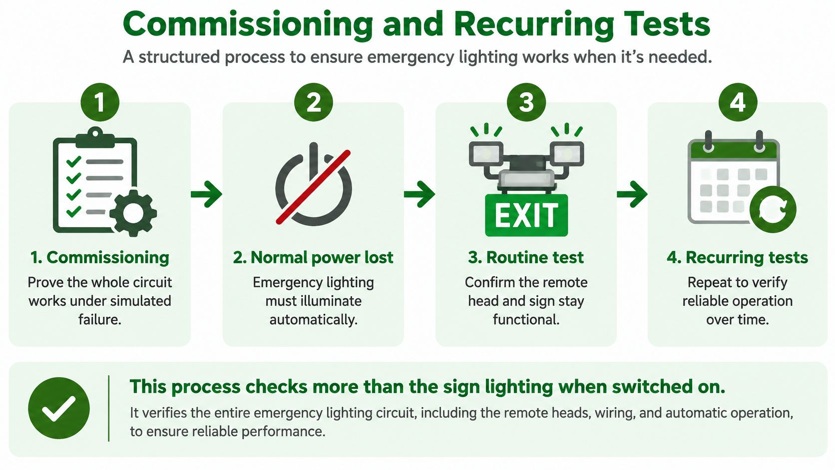
A commissioning test proves the whole circuit under a simulated failure. Switching the sign on at the wall only proves the legend has power today.
Under NFPA 101, emergency lighting must automatically illuminate when normal power is lost and remain available for at least 90 minutes. That duration applies whether remote heads run from an integral battery or from a centralized emergency-power system. The same guidance calls for monthly functional tests of at least 30 seconds and an annual 90-minute test, with inspection and test records retained.
The installer has to confirm that battery or inverter capacity, conductor voltage drop, remote-head wattage, and total connected load all fit together. Adding heads raises emergency current demand. An undersized unit shortens runtime or delivers low-voltage light that dims heads without a blown lamp you can point at.
Prove the circuit before handover
- Confirm charging. The battery and power unit are connected and charging on normal power.
- Confirm voltage at each head. Every remote head is wired to the voltage it is rated for.
- Kill normal power to the panel so the transfer isn't a button push on the sign.
- Watch every lamp. The sign and each remote head have to come on, not just the nearest one.
- Time a discharge of at least 90 minutes and check light at the far end of the route, not only at the unit.
- Restore power and confirm the system returns to charge.
- Write the record with the date, the runtime, and any failed lamp or LED on each head.
A head that lights for a short push-to-test can still die before the full duration if the load is too high. If runtime comes up short, reduce the connected load or upsize the power unit. Don't "pass" a short test and hope the battery has more in it.
A lamp that comes on is not a lamp that stays on.
Low-voltage output is the quiet failure. Heads look lit, the indicator may look normal, and the far end of the corridor is still too dim to walk. That's why the far-end check belongs in the timed test, not in a glance from the electrical room. Emergency lighting testing is the habit that catches that fade before an inspector does.
After the building is occupied
| Task | Frequency | Pass standard | Record |
|---|---|---|---|
| Functional test of sign and remote heads | Monthly | Every lamp lights for at least 30 seconds | Date, unit, any failed head |
| Full discharge test | Annually | Runs for at least 90 minutes on battery | Runtime, light output at far end, result |
| Battery replacement | Per manufacturer replacement date | Battery holds rated runtime | Installation date and replacement date |
| Load recalculation | Whenever heads are added or moved | Total connected load within unit rating | Updated load sheet |
Recalculate the load every time someone adds or moves a head. A renovation that "only" adds two heads can push the unit past its rating with no change to the sign face.
Keep one file. Label the power unit and each remote head. Store the battery replacement date, each test result, any failed lamp or LED, and the latest load sheet together. Asset labeling turns a simple-looking exit sign into a circuit you can maintain. When an inspector asks which head failed in March, you shouldn't be opening three binders.
Walk the Route Before Your Next Inspection
Bring the marked floor plan, the head model numbers, the latest test log, and the battery dates. Walk the route with a light meter and a tape, and treat every head as part of the same circuit.
- Read illuminance at each sign face and compare it with the visibility rule for the legend.
- Measure the Exit letters for height and principal stroke width.
- Check coverage and sightline from each head to the next head and to the exit.
- Confirm rated voltage at every head and that each cable length is written down.
- Match the log and battery dates to the test schedule.
A single failed head, or a missing line in the log, is the usual reason a system fails review. Cover every head. Mark each gap for correction before the inspection date, not during the walk-through with the inspector beside you.
Confirm local amendments and occupancy rules with the authority having jurisdiction. We install, maintain, and test emergency lighting, battery backup systems, and exit signs so properties can meet those local safety codes. Access Electrical and Lighting is a licensed and bonded California C-10 electrical contractor, license 952234. After-hours failures go to our 24/7 line at (949) 364-6063. Book the compliance check before the inspection is on the calendar.
Access Electrical and Lighting installs, maintains, and tests emergency exit signs with remote heads as one circuit, including the heads, the battery backup, and the written test record inspectors ask for. If your corridor goes dark past the sign, or a discharge test keeps coming up short, we can walk the route with you and correct the gaps. Visit Access Electrical and Lighting to schedule that check before your next inspection.