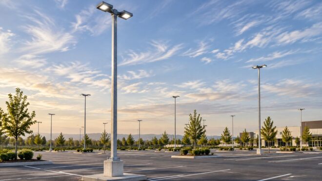
A row of lot lights has started failing, and the replacement quote focuses on LED fixtures and wattage. Before approving it, check what each pole must carry, where it sits relative to moving vehicles, and whether its base can still do its job. A cheaper fixture retrofit can become an expensive mistake if the pole, foundation, or attachments aren't suited to the new setup.
Parking lot lighting poles also run for long nightly schedules. The U.S. Department of Energy's federal parking-lot guidance says exterior lots commonly operate for more than 13 hours per day, which makes control choices and reliable maintenance important parts of the project, not just add-ons (U.S. Department of Energy parking-lot guidance).
Parking Lot Light Pole Types and Typical Heights
A manager replacing a row of failed lights needs to know what the poles must support before choosing a height. Each one carries a luminaire, wiring, and wind forces, while occupying space in a vehicle environment. The right choice balances light coverage, structural demand, access for maintenance, and the available pole locations.
| Pole type | Typical height | Typical use | Typical spacing approach | Typical luminaire load |
|---|---|---|---|---|
| Pedestrian and walkway pole | 12–16 ft | Plazas, paths, low-level walkways | Close spacing for pedestrian-scale coverage | Single, lower-output fixture |
| Standard area pole | 20–30 ft | Typical lots and drive aisles | Regular spacing based on the photometric layout | Single area-light head |
| Taller lot pole | 30–40 ft | Wide aisles, fewer poles per acre | Wider spacing, verified for uniformity | Higher-output or multiple fixtures |
| High-mast pole | 40–80 ft | Large open lots, truck yards, transit areas | Broad coverage planned as a system | Larger or multiple fixtures and accessories |
These are planning categories, not a substitute for a site design. The actual spacing and equipment load must suit the fixture optics, pole location, and required light distribution. A single fixture head may have a different wind profile from a cluster, even if the equipment weights are similar.
How height changes the trade-off
A taller pole can spread light over a broader area and may reduce the number of poles needed. But height also increases the bending moment at the base, and higher fixtures are harder to inspect or service. If the design compensates for a dark area by choosing a taller pole or a more powerful luminaire, it can add structural demand and glare without fixing poor placement or optics.
Shorter poles can be easier to access and may suit walkways or constrained sites. They often require more carefully planned locations to avoid dark gaps and may mean more foundations, conduit, and equipment. A photometric layout should establish whether the proposed height, fixture distribution, and spacing produce suitable coverage before poles are ordered.
Practical rule: Choose the shortest pole that meets the light-level target, then confirm its structural rating and foundation design before ordering.
The material choice affects strength, weight, corrosion resistance, and maintenance, so match the pole type to the site rather than selecting by height alone.
Materials and Coatings That Hold Up in Coastal Southern California
At coastal sites, moisture and salt can attack a pole where water collects near grade, around the handhole, or at damaged coating. That makes the base a priority during both specification and inspection. The best material depends on the height, loading, location, and appearance the property needs.
| Material | Strength and weight | Corrosion behavior | Typical coating | Best fit |
|---|---|---|---|---|
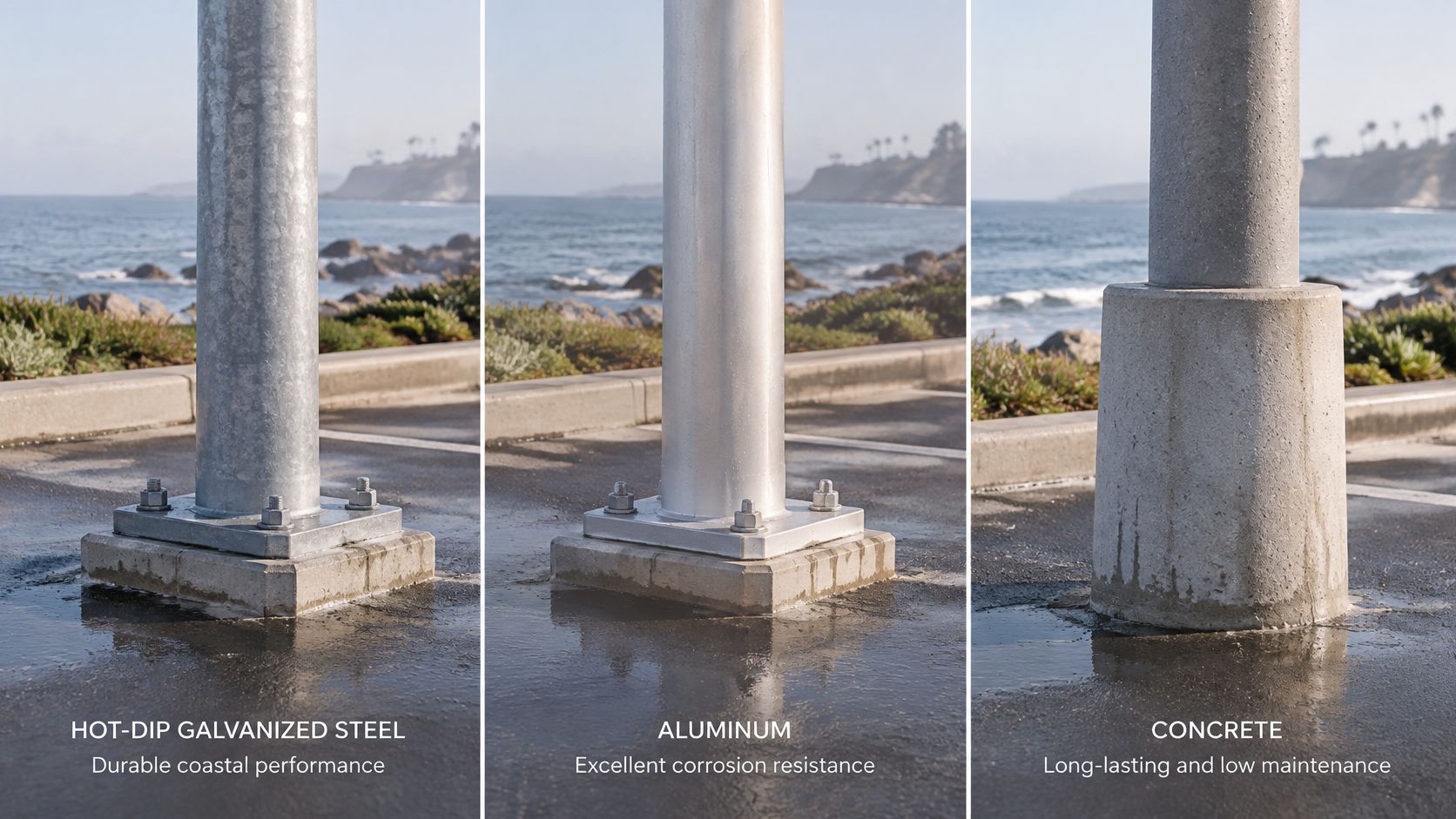
| Hot-dip galvanized steel | High strength, heavy | Zinc protects well; damage at welds and cut ends needs attention | Galvanizing, with compatible touch-up at damaged areas | Tall lot and high-mast poles |
| Aluminum | Lighter, lower strength per pound | Does not rust; resists salt air well | Protective finish selected for the site | Shorter poles and sites close to the coast |
| Precast or concrete | Rigid and heavy | Does not rust; cracks and spalls if rebar is exposed | Concrete surface protection as specified | Low decorative and pedestrian poles |
Specify the weak points, not just the finish
Hot-dip galvanizing is a durable base layer for steel, but it doesn't make damage irrelevant. Welds, cut ends, and areas disturbed during installation need compatible repair coatings. If a pole receives a powder coat for color and added protection, specify the complete system over the galvanized surface rather than treating the powder coat as a replacement for galvanizing.
Paint alone is generally the least forgiving option at a wet, exposed base. Once the coating is damaged, corrosion can spread under the paint and become hard to assess from a quick drive-by. For any material, detail how the finish continues around the handhole and base plate, where inspection and water management matter.
Concrete poles avoid steel corrosion, but they're not maintenance-free. A crack or spall that exposes reinforcing steel creates a deterioration path, so check the condition rather than assuming a rigid pole is sound.
Make a short base inspection part of the property's annual routine. Look for rust bleed, cracks, standing water, and coating damage, and investigate signs that reach the pole or its foundation instead of hiding them under a cosmetic patch.
Wind Loading and Attachments That Overstress Poles
A crew replaces an old fixture with a lighter LED head, then adds a shield and a security camera. The total weight may have gone down, but the pole could still face greater wind demand because those additions change the area exposed to wind and the way the load acts on the shaft.
Pole height and attachment area both matter. A taller pole increases the bending moment at its base, while wind acting on a luminaire, banner, camera, or sign adds overturning demand. Engineers commonly use AASHTO, the International Building Code, and ASCE-based wind maps; calculations generally use a 3-second gust wind speed referenced at 33 feet (10 meters) above grade. The applicable wind criteria and effective projected area must match the actual site and pole configuration, as explained in this pole-design guide on wind speed and effective projected area.
Why a lighter fixture can still be a problem
Weight is only one input. A broad fixture shield, camera housing, or sign can present more surface area to the wind than the previous equipment. The pole's height and mounting arrangement then affect how that force transfers to the base. A retrofit that changes the head or adds accessories can invalidate the original design even if the replacement equipment weighs less.
Coastal Southern California adds another concern: corrosion can reduce the margin the original design relied on. A pole that appears straight may still have deterioration at a weld, handhole, anchor bolt, or base plate. Don't infer structural capacity from appearance alone.
Retrofit checks before installation
Before adding or changing equipment, assemble the pole manufacturer's data and compare the proposed configuration with the original design. Check the original design wind speed and exposure category, then inventory every attachment, including items added after the pole was installed.
Inspect the shaft, welds, anchor bolts, base plate, and foundation before work proceeds. If a high-mast pole is involved, ask the engineer whether fatigue evaluation is needed, since repeated wind-induced stress can govern service life. Keep the equipment schedule with the pole records so a later camera or banner addition doesn't go undocumented.
The useful question isn't whether the LED head fits the mounting arm. It's whether the pole, base, and foundation remain suitable with all proposed attachments in place.
Pole Placement, Impact Protection and Light Levels
The cheapest retrofit can preserve a vulnerable pole location because moving it costs more. Then a vehicle strike can turn the pole into an electrical hazard and create an access or liability problem. A lighting plan that ignores vehicle paths and pole protection can save on installation while leaving the site exposed to a predictable kind of damage.
Federal facilities guidance recommends placing poles outside vehicle clear zones or behind barriers, or using breakaway designs. Where a pole must sit within parking rows, it recommends placing it at the junction of adjacent stalls and using a concrete base about 3 feet high to reduce accidental knockdowns. The same guidance identifies typical pole heights of 20–50 feet or more, a normal parking-lot lighting level of 1–2 foot-candles, and a maximum-to-minimum uniformity ratio no greater than 20:1 (federal facilities guidance on lighting for traffic safety).
Place poles for protection first
Start with the vehicle clear zones and likely impact paths, then look for positions behind barriers or other protection. If a pole has to sit in a row, place it where the parking layout offers the best separation from moving vehicles. A breakaway design may be appropriate in some locations, but it still has to suit the pole's electrical and structural requirements.
Retail, multifamily, and office sites deserve a careful placement review because poles sit alongside everyday vehicle and pedestrian movement. A damaged base or anchor-bolt assembly should prompt a structural assessment, not a quick cosmetic repair.
Verify the light after a move
Physical protection and light distribution have to work together. Moving a pole to reduce collision risk changes the geometry of the lighting plan, so recalculate the coverage and uniformity rather than assuming the existing fixture will still illuminate the same areas. Oversized poles can increase wind and foundation loads; shorter poles may require more poles and foundations.
For a project-wide review of placement, coverage, and fixture arrangement, use parking lot lighting design guidance. Confirm the local requirements as well as the photometric results, and make sure a safer pole location doesn't create a dark area along a drive aisle, accessible route, or building entrance.
How to Set the Foundation, Mount and Wire the Pole
A sound installation depends on a sequence that keeps the pole location, anchor assembly, electrical route, and fixture configuration aligned. The engineer's drawings and equipment instructions govern dimensions and torque values. Rushing the foundation or leaving wiring details until the pole is standing can create costly access and alignment problems.
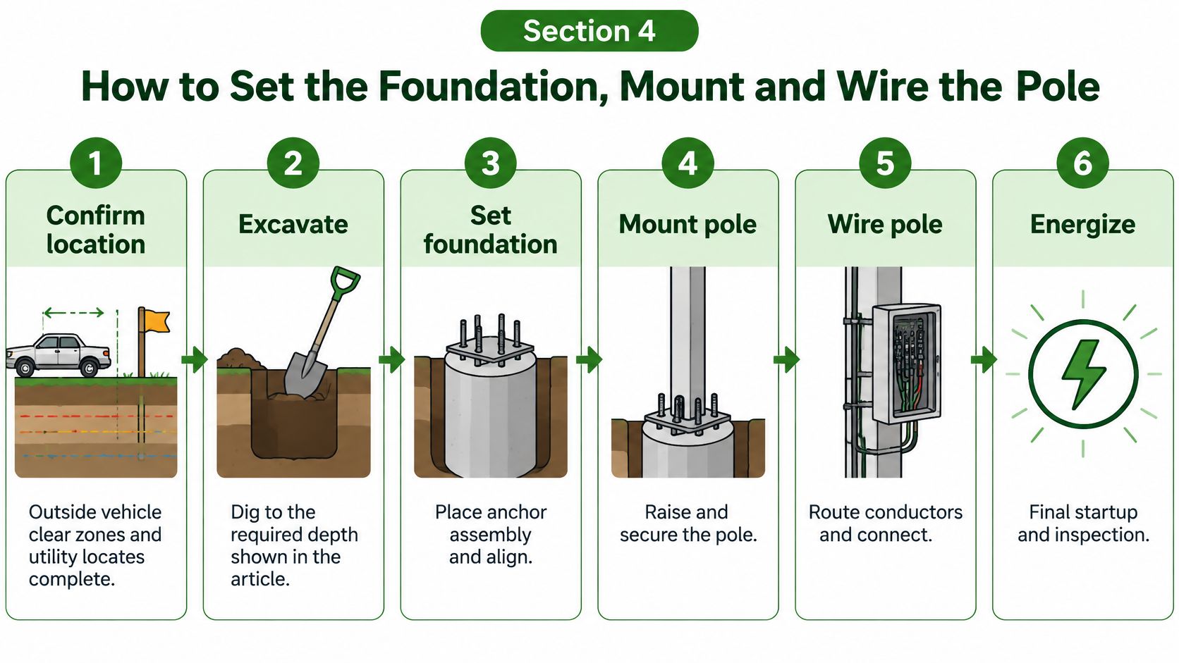
Confirm the location. Verify that the base is outside vehicle clear zones or appropriately protected, and complete utility locates before excavation. A pole location that conflicts with buried services or vehicle movement can force a late redesign.
Excavate to the engineered depth. Follow the depth and foundation details in the engineer's drawing, not a generic field rule. Check the excavation against the plan before placing the anchor assembly so the foundation dimensions and pole position match the design.
Set the anchor assembly and pour the foundation. Use the correct template to hold the anchor bolts at the specified bolt circle, elevation, and orientation. Check that the template is level before concrete placement; a misaligned assembly can prevent the base plate from seating properly.
Allow the foundation to cure, then mount the pole. Don't load the foundation before it has reached the condition required by the project documents. Set the pole on its base plate, plumb it, and tighten the anchor-bolt nuts in the manufacturer's specified sequence and to the specified torque.
Route and connect the wiring. Bring the conduit and grounded circuit into the handhole, leaving enough service slack for safe work and providing a clearly labelled disconnect. Undersized conduit can make future conductor replacement difficult, so confirm the conduit plan before the concrete work is complete.
Mount the luminaire and accessories. Install the fixture and any approved camera, shield, sign, or other attachment in the planned positions. Record the complete equipment configuration, including the projected area of attachments, so the as-built pole matches the design review.
Test, then energize. Test insulation resistance and ground continuity, and document the results before applying power. Once energized, verify that the photocell switches correctly and that the fixture operates as intended.
A proper handover includes a plumb pole, anchor nuts torqued and recorded, a labelled disconnect, and written test results. Keep the pole and circuit details with the site's maintenance records so the next crew can identify what was installed and how it was verified.
Controls and LED Retrofits That Cut Energy Use
A retrofit that saves energy on paper can still fail the site if it leaves drivers walking through dim lanes or puts extra hardware on poles that were never checked for the added area. Wattage matters, but control zones, optics, schedules, impact exposure and what is bolted to the shaft decide whether the cheaper scope is cheaper.
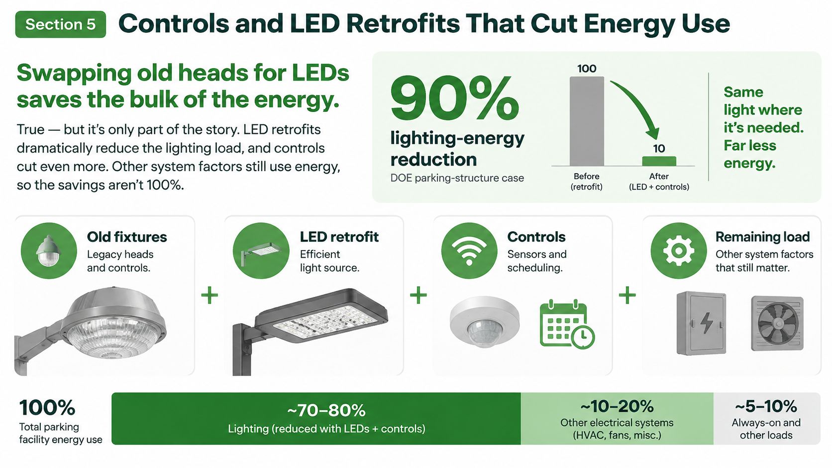
In federal parking-lighting case studies and control guidance, a U.S. Department of Energy parking-structure case documented a 90% reduction in lighting energy after replacing low-wattage high-pressure-sodium fixtures with efficient LEDs and lighting controls, lighting power density also fell 70%, and a separate PNNL demonstration reduced LED output from 102 watts to 68 watts when no movement was detected, a 33% reduction. Treat those results as evidence that controls and verified design belong in scope, while savings still have to be proven site by site.
Model the whole control zone
Motion controls can substantially cut the input power of outdoor parking luminaires during periods of inactivity, but the sensor zones must be laid out around the actual fixture optics and pole spacing. A sensor that looks acceptable in plan can leave the drive aisle active while pedestrian corners go dark, or trigger every fixture on the circuit when only one pole should respond.
For California projects, California Title 24 outdoor-lighting control guidance describes automatic scheduling controls that reduce outdoor-lighting power by 50–90% during scheduled unoccupied periods and motion-sensing controls generally required for parking-lot luminaires below 24 feet; one municipal standard cited in that guidance turns most parking-lot lighting off 30 minutes after business closing, retains security lighting, and limits light at the property line to 0.5 foot-candles. Local standards can add their own operating and property-line limits.
Define security zones and dimming levels before commissioning. Set sensor zones and timeouts to avoid nuisance activation, and confirm that dimmed operation still provides suitable visibility where people walk and vehicles turn. Before adding sensors, shields, cameras or signs, confirm the pole, base plate, anchor bolts and foundation still have capacity for the revised projected area; a low-wattage head is no bargain if the attachment makes an older pole the weak point.
A retrofit should finish with checks for maintained illuminance, uniformity, fixture aiming, control timeouts, and emergency-lighting behavior. Document the control sequence and the required Title 24 performance. For a project focused on replacing existing site fixtures, see LED retrofit services for parking lot lights.
Integrity Testing and a Maintenance Schedule
A pole can look straight from the drive lane while rust bleed or a hairline crack hides under its cover. A quick visual pass is useful, but it can miss defects at the base, handhole, connections, or anchor assembly. Build a routine that combines observation with hands-on checks and documented specialist testing.
| Inspection | Frequency | What to check | Action when found |
|---|---|---|---|
| Visual walk-around | Quarterly | Lean, base cracks, rust bleed, missing covers, water in handhole | Log the finding; schedule repair if the base is affected |
| Hands-on hardware check | Annually | Anchor-bolt torque, grounding, photocell, connections | Re-torque or replace the fastener; repair the connection |
| Infrared thermography | Annually | Hot connections and fixture hotspots | Schedule corrective work before failure |
| Integrity testing | Every 3–5 years, sooner on coastal sites | Shaft, welds, base plate, anchor assembly | Repair minor defects; replace compromised poles |
| Post-impact or post-storm inspection | After any event | Structure, base, wiring, and fixture before re-energizing | Don't re-energize until cleared |
Match the inspection to the risk
During a walk-around, look for a change in alignment, cracks near grade, corrosion, missing handhole covers, and standing water. Record the pole location and finding so the maintenance team can spot a developing pattern instead of treating each visit as a fresh inspection.
The annual hands-on check should include hardware, grounding, photocell operation, and visible electrical connections. Infrared thermography can identify hot connections or fixture hotspots without direct contact, giving the team a reason to schedule corrective work before a component fails. After a vehicle impact or storm, inspect the pole, base, wiring, and fixture before re-energizing it.
Integrity testing is a documented specialist assessment of the shaft, welds, base plate, and anchor assembly. Coastal exposure, corrosion, or a known impact can justify earlier testing than the routine interval. If the base or anchor assembly is compromised, don't treat a surface patch as proof that the pole is structurally sound.
Keep dated inspection notes, photographs, and test results together. Those records help track corrosion or loosening over time and support a clear account of what was checked and repaired. Access Electrical & Lighting provides parking-lot light maintenance for property teams planning routine inspections and repairs.
Call for an immediate assessment if you find a leaning pole, a cracked base, loose anchor nuts, or a hot electrical connection. Keep people clear of a damaged pole, and don't restore power until the structure and electrical system have been checked.
Decide Repair, Replacement or Upgrade for Each Pole
Give each pole one of three outcomes: repair, replacement, or upgrade. The right choice depends on the condition of the base and shaft, the loads the pole must carry, and whether the fixture or control plan is changing.
Repair when the shaft and base remain sound and the defect is limited to a fastener, connection, or cover. Correct the specific failure and document the work.
Replace when the base, anchor-bolt assembly, or shaft is compromised. Patching a failed base rarely restores the original design margin, so assess the full pole and foundation before deciding what stays.
Upgrade when new fixtures, controls, or attachments change the system. Check wind and loading before adding equipment, then confirm that the proposed control strategy fits the site. The California Title 24 guidance emphasizes scheduling, sensing, and documented performance rather than fixture wattage alone (Title 24 outdoor-lighting control guidance).
Compare project quotes by access, crew time, trenching, foundation work, and whether the pole itself must be replaced, not by fixture wattage alone. If EV charging is a future possibility, assess panel capacity, conduit, trenching, pole loading, and nighttime access before treating the lighting pole as a potential electrical platform.
Start with a documented integrity test and a lighting survey, then rank poles by risk and sequence the work. Access Electrical & Lighting offers light pole replacement and integrity testing, along with complimentary lighting surveys to assess a property and recommend energy-efficient lighting solutions.
If your lot has failing fixtures, questionable bases, or poles carrying new equipment, Access Electrical and Lighting can help assess the lighting, test pole integrity, and plan repairs or replacement. Request a complimentary lighting survey to identify practical improvements for your property.