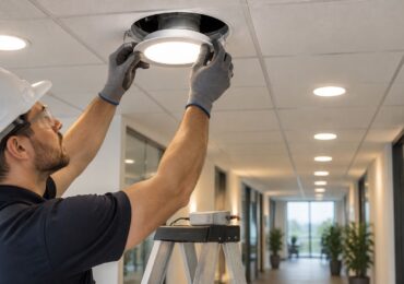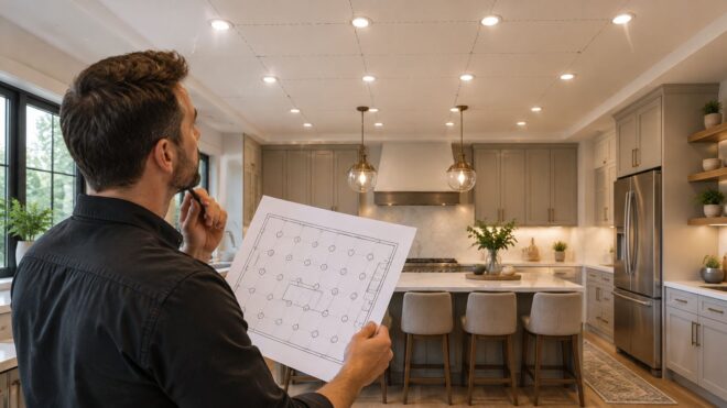
You've got a floor plan, a ceiling full of possible fixture locations, and an electrician asking where the lights should go. An evenly spaced grid looks sensible on paper. But will it light the counter, reflect in the office screens, or leave bright arcs across the lobby wall?
Learning how to design recessed lighting layout starts with geometry, but it doesn't end there. A workable plan connects fixture placement, photometric performance, controls, and ceiling construction before anyone orders equipment or cuts holes.
Spacing Grid Starting Points by Ceiling Height
Start by drawing a loose grid, not by committing to a fixture count. The OhmNexus recessed-lighting calculator describes the preliminary method of spacing downlights approximately half the ceiling height apart, with the first row approximately half that spacing from the wall.
The table applies that arithmetic to several ceiling heights. Its check-range column is a multiplication exercise using the factors shown, not a manufacturer-approved spacing recommendation.
Starting spacing by ceiling height
| Ceiling height | Starting spacing, center to center | First row from wall | Check range, 0.5 to 0.8 times height |
|---|---|---|---|
| 8 ft | 4 ft | 2 ft | 4 to 6.4 ft |
| 9 ft | 4.5 ft | 2.25 ft | 4.5 to 7.2 ft |
| 10 ft | 5 ft | 2.5 ft | 5 to 8 ft |
| 12 ft | 6 ft | 3 ft | 6 to 9.6 ft |
| 16 ft | 8 ft | 4 ft | 8 to 12.8 ft |
Read the shorter-ceiling rows as a way to establish an initial rhythm. The intermediate row interpolates the same geometry. The taller-ceiling rows continue the arithmetic, but they don't prove that light will reach the intended surface with adequate brightness.
Center-to-center spacing means measuring between fixture centers, not between the edges of their trims. Likewise, measure the wall offset to the center of the first fixture row.
Separate ceiling height from working height
The check-range column uses full ceiling height as a quick proxy. Actual spacing checks use the distance between the luminaire and the workplane, which might be a desk, counter, or floor. For a raised task surface, subtract its measured height before applying the fixture's spacing criterion.
Sketch test: Draw the wall rows, furniture, counters, desks, and artwork before treating the grid as a layout.
Then inspect each fixture's purpose. A ceiling dot centered beautifully between walls may sit behind someone working at a sink or directly above a reflective desktop.
Beam distribution, delivered output, surface reflectance, and irregular room boundaries can all change the sketch. Keep the grid movable until the selected fixture's photometry confirms it.
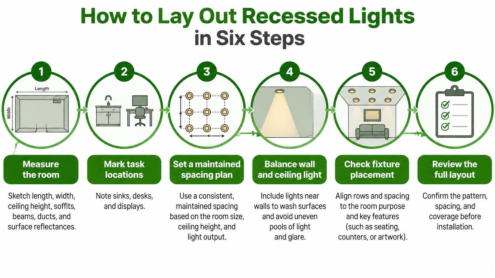
How to Lay Out Recessed Lights in Six Steps
A fixture count becomes useful only when you know what the room needs and what the fixture delivers. The Bock Lighting layout guidance supports a room-by-room photometric workflow, including the lumen-method calculation and a preliminary spacing check using mounting height above the workplane multiplied by a spacing-to-mounting-height ratio, commonly 0.5 to 0.8 for downlights.
Establish the room and its requirements
Measure the room and mark the tasks. Record length, width, ceiling height, soffits, beams, ducts, and likely surface finishes on a reflected ceiling plan, which shows the ceiling as viewed from below. Locate sinks, desks, displays, and furniture so you don't design an empty room that nobody will occupy.
Choose a maintained illuminance target. Set the required light level at the relevant surface, allowing for output loss and dirt over time rather than judging only a new installation. The common slip is assigning one target to an entire property even though reading documents, walking through a hallway, and viewing merchandise require different decisions.
Illuminance targets by space
| Space | Target, foot-candles |
|---|---|
| General office work area | Set for the actual desk task, screen use, and applicable design criteria |
| Retail sales floor | Set for merchandise, display contrast, and the intended shopping environment |
| Home kitchen general light | Establish an ambient target, then assess food-preparation surfaces separately |
| Corridor or hallway | Set for circulation, transitions, and applicable emergency-lighting criteria |
Don't fill those cells with an attractive-looking universal number. Have the lighting designer document the selected targets and their basis before comparing fixture options.
Select, calculate, and verify
Select the luminaire by performance. Compare delivered lumens, distribution, glare characteristics, color quality, dimming compatibility, and thermal or insulation ratings. A nominal fixture size or advertised wattage doesn't tell you whether its light will reach the right surface.
Estimate quantity with the lumen method. Calculate fixture quantity = (area × target illuminance) ÷ (delivered lumens per fixture × coefficient of utilization × light-loss factor), then round up. Use compatible units, square feet with foot-candles or square meters with lux, and don't omit the light-loss factor merely to achieve a lower fixture count.
Place and adjust the preliminary grid. Fit the fixtures around task locations, ceiling obstructions, and the intended wall illumination rather than forcing every room into equal rows. The common mistake is moving a fixture around a duct without checking what happens to the light below it.
Model the complete layout. Load the manufacturer's photometric file into lighting-calculation software and assess average illuminance, minimum illuminance, uniformity, vertical illumination, and glare. Include other lighting layers so the recessed fixtures aren't calculated as though they're the room's only light source.
A useful calculation package shows the workplane, calculation points, fixture schedule, and assumptions. In areas intended to be evenly lit, the minimum shouldn't fall into isolated dark pockets far below the average. Task surfaces should also remain free of distracting hot spots, even when the overall average meets the target.
Picking Trim, Beam Angle and Lumen Output
Choose the trim for the surface and sightline, not just the ceiling appearance. These options can look similar in a catalog while producing quite different results in an occupied room.
Trim types matched to tasks
| Trim type | Best use | Watch for |
|---|---|---|
| Baffle trim | General light in offices and living rooms | Can reduce delivered output compared with a comparable open trim |
| Reflector trim | Broad general light and compatible retrofit applications | Bright reflector or source may be visible at close range |
| Adjustable gimbal trim | Accent light on art, displays, and niches | Requires careful aiming and a check from occupant sightlines |
| Wall-wash trim | Walls, art panels, and merchandise faces | Requires coordinated wall offset, spacing, and orientation |
Baffle trims are a sensible starting point where people sit beneath fixtures or view them across a room. Their internal shielding can make the source less conspicuous, but compare the complete luminaire's delivered output rather than assuming every baffle performs alike.
Reflector trims suit general illumination when their distribution matches the room. Don't assume that a shiny interior guarantees comfort. Examine how much of the luminous opening a seated occupant can see.
Match the beam to its destination
An adjustable gimbal lets you direct light toward a feature instead of directly downward. Check its aiming limits before placing the ceiling opening, especially when the target is high on a wall.
A wall-wash trim serves a different purpose: distributing light across a vertical surface. It isn't interchangeable with a general downlight placed near the wall.
- Narrow distributions: Use for selective emphasis, with careful aiming and attention to contrast.
- Medium distributions: Consider for localized tasks and controlled general illumination.
- Wide distributions: Consider for overlapping ambient coverage, subject to the actual photometric pattern.
Lumens describe output, not brightness at the task. Our explanation of foot-candle-to-lumen conversion helps distinguish fixture output from the illumination reaching a surface.
Match the trim finish to the ceiling if you want the opening to recede visually. Confirm the complete housing, trim, and light-engine combination is approved for the installation conditions. Don't substitute a different trim after calculations without checking whether its distribution or delivered output changes.
Why Wall Scallops and Glare Ruin Recessed Layouts
An evenly spaced ceiling grid doesn't guarantee an evenly lit room. The Department of Energy's high-performance lighting guide warns that downlights close to walls can create scallops and that layouts intended for ceilings up to 10 feet may need higher-wattage fixtures at greater heights.
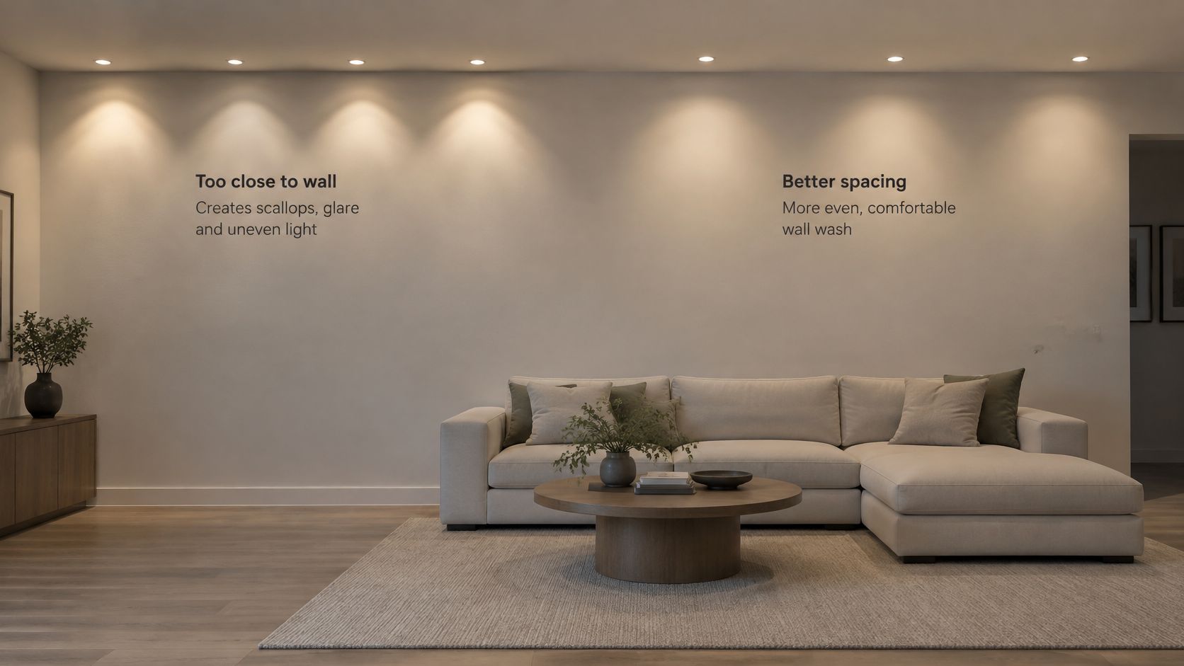
A scallop is the visible arc formed where a light distribution intersects a wall. Repeated bright arcs and dark gaps can make an otherwise orderly lobby look uneven, particularly across an uninterrupted painted surface.
Glare is a separate problem. A fixture can deliver adequate illumination while exposing a bright source in someone's normal view or creating a reflection on a polished surface.
Design for what people actually see
In a retail space, inspect glossy counters and merchandise from customer viewing positions. At computer workstations, check screens from seated eye level. In corridors and hospitality areas, consider the long view toward the fixtures, not merely the floor beneath them.
A uniformly bright floor isn't always the most comfortable or useful lighting result.
A deliberately illuminated wall can make a room feel brighter without raising the output of every ceiling fixture. Artwork may need controlled accent light, while faces at a reception desk may need a complementary lighting layer rather than more overhead intensity.
Choose beam distribution, output, wall offset, spacing, and shielding together. Moving a row closer to a wall isn't a substitute for specifying wall-washing optics.
Validate difficult conditions with a photometric model or an on-site mock-up using the intended fixture and representative finishes. Review it from occupied positions with adjacent lighting operating. That check is particularly valuable in tenant improvements and multifamily common areas, where existing finishes and fixed ceiling conditions limit your options.
Zoning Dimmers and Sensors for Each Room
Draw control-zone boundaries on the ceiling plan while fixture locations are still adjustable. Fixtures should share a control because people use them together, not just because they happen to sit in the same row.
An EIA review of lighting sensors and controls reports average lighting-energy savings of about 24% from occupancy controls and 20% to 60% from photosensors in cited case studies. Those findings describe evaluated applications, not guaranteed savings for a particular property.
Assign controls by use
- Perimeter and daylit areas: Separate fixtures receiving useful daylight from deeper interior fixtures so daylight response doesn't leave the interior underlit.
- Private offices and dwelling rooms: Provide accessible manual operation and appropriate dimming, with occupancy or vacancy sensing where applicable.
- Corridors and bathrooms: Check detection coverage at entrances, around corners, and behind partitions so the control responds to actual use.
- Display and task areas: Keep accent lighting independently adjustable when its operating schedule or brightness differs from ambient lighting.
Occupancy sensing turns lights on or changes their operation when people are detected. Vacancy sensing generally relies on manual activation with automatic shutoff. Choose the behavior deliberately, and document manual overrides rather than leaving the installer to interpret the intended operation.
Our guide to automated lighting controls explains how these functions fit into a coordinated system. Confirm driver and dimmer compatibility before procurement, including the intended low-end dimming performance.
Commission the occupied space
During commissioning, test sensor coverage, timeout behavior, daylight setpoints, scenes, and dimming range. Measure illumination under the relevant operating conditions, and verify emergency operation so normal control failures don't compromise required egress lighting.
Handover requirement: Give the owner the control-zone drawing, operating instructions, and recorded test results, not just a demonstration that the lights switch on.
Correct sensors that detect neighboring spaces, perimeter fixtures omitted from daylight control, and drivers that flicker or drop out during dimming. Document the final settings so maintenance staff can preserve the intended operation.
Code Checks, Rough-In and Go-or-Revise Check
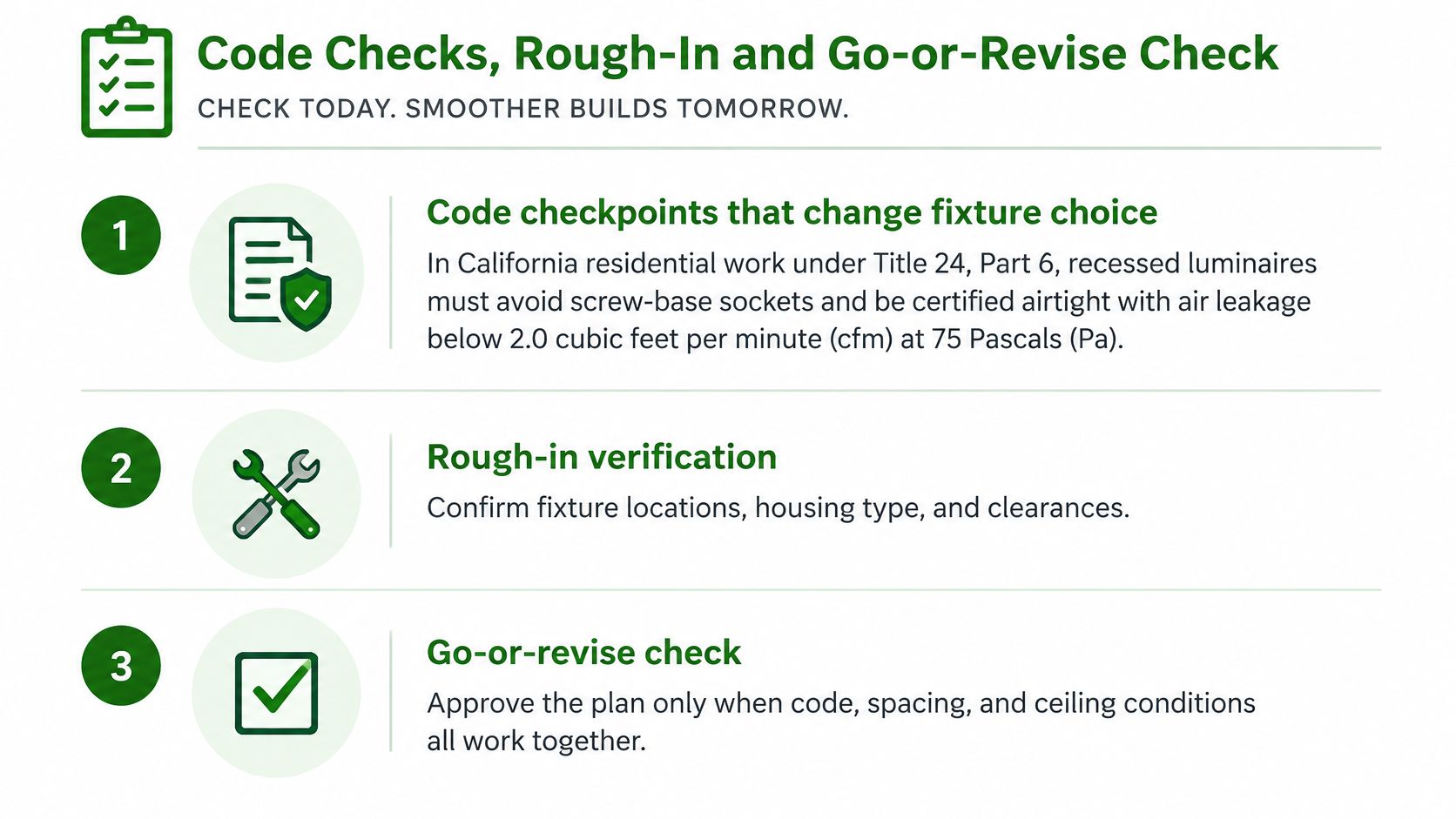
California code can change the fixture specification before it changes the drawing. For covered residential work, the California Energy Code residential provisions require recessed ceiling luminaires without screw-base sockets, certified airtight with leakage below 2.0 cubic feet per minute at 75 pascals under ASTM E283, sealing between housing and ceiling, and installation consistent with California Electrical Code Article 410.116.
The airtightness clause deserves a second look, because it reframes what a recessed fixture is. Every housing punches an opening through the ceiling's thermal boundary, and an unsealed fixture lets conditioned air escape into the space above whenever the building pressure pushes it there. The code rates that opening by airflow, which is why a decorative trim cannot rescue a leaky housing.
Those same provisions require readily accessible manual on/off and dimming controls in habitable rooms. Bathrooms, garages, laundry rooms, utility rooms, and walk-in closets need at least one luminaire controlled by an occupancy or vacancy sensor with automatic-off. That second requirement reaches back into your zone boundaries: a bathroom sensor cannot share the adjoining bedroom's dimmer, so zones have to follow code categories rather than convenience.
Commercial and multifamily projects follow a different checklist. Common areas, corridors, and parking structures fall under nonresidential provisions, so confirm the applicable project classification, adopted code edition, and local requirements with the permitting authority before applying any residential rule. Our overview of Title 24 lighting requirements provides context for coordinating that review.
Verify the ceiling before rough-in
Compare the selected housing depth with the space available, including joists, ducts, pipes, and driver enclosures. Check insulation-contact suitability and the manufacturer's clearance instructions for the complete assembly. A shallow visible trim proves nothing about the equipment above it.
- Assembly coordination: Confirm compatibility with fire-rated construction and preserve required air barriers.
- Service access: Establish how drivers and replaceable components can be reached without damaging finished construction.
- Wiring coordination: Label control zones, identify circuit assignments, and calculate connected loads before rough-in.
- Documentation: Record fixture models, approved combinations, applicable certification markings, and installation requirements.
A field relocation should trigger a drawing update and a fresh lighting check. An obstruction that shifts one fixture can break the spacing grid and change the wall scallops the layout was built around, so an undocumented "convenient" opening is really a different lighting design wearing the old one's name.
Approve or revise the complete plan
Approve procurement only when the calculation meets the documented illumination criteria, the intended wall appearance is acceptable, and each zone has a defined control. The fixture schedule should identify the selected equipment and quantity, and the calculation should record its utilization and light-loss assumptions.
Revise the plan if ceiling conflicts remain unresolved, service access is unclear, or a proposed substitution lacks photometric and installation documentation equivalent to the specified fixture. Commercial and multifamily projects also need a coordinated emergency and egress review before approval.
The review itself goes faster when the documentation arrives complete. Bring the room dimensions, ceiling heights, intended uses, sketched grid, fixture schedule, and control plan, and confirm any applicable JA8 marking requirements with the inspector before ordering, while substitutions are still free.
Once the plan passes that check, put it in front of a contractor. Access Electrical and Lighting offers complimentary lighting surveys that assess brightness levels, fixture placement, and energy consumption, then recommend the most energy-efficient improvements for the property. Contact the team to schedule one, and bring your floor plan, ceiling heights, and intended room uses so the conversation starts from your actual layout rather than a generic grid.