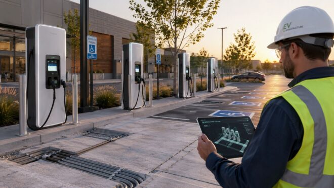
A property manager usually starts with a simple request: add a few EV chargers near the best parking spaces. The surprise comes later, when an electrician opens the service equipment and finds that the building is already carrying substantial continuous loads, the electrical room is full, and the utility transformer has little practical headroom.
That's why EV charging station design isn't a charger-selection exercise. It's a whole-site decision involving electrical capacity, parking geometry, fire safety, accessibility, communications, permitting, and future expansion. A charger that looks ideal in a vendor brochure can become an expensive problem once conduit routing, load calculations, utility requirements, and inspection conditions enter the picture.
Why EV Charging Station Design Starts Before the Charger
A retail property manager once approached a project with a straightforward plan: install eight Level 2 chargers at a 180-stall shopping center. The property had an 800 A service, so the initial assumption was that adding EV charging would be routine. The electrical review found only 90 kW of usable headroom, and the proposed installation forced a $180,000 utility upgrade.
That scenario captures the mistake I see most often. The team chose the charger count and hardware before confirming whether the site could support them. The equipment decision came first, while the service rating, existing continuous loads, transformer availability, and feeder path were treated as details to solve later.
The correct order runs upstream:
- Confirm the electrical service. Review the service rating, main distribution equipment, transformer, and utility capacity.
- Map existing loads. Account for HVAC, lighting, elevators, refrigeration, domestic water equipment, and other continuous building loads.
- Model the charging demand. Evaluate the proposed charger portfolio under realistic simultaneous-use conditions.
- Lay out the parking. Check stall access, pedestrian movement, ADA requirements, cable reach, fire clearances, and vehicle protection.
- Select hardware and controls. Choose Level 2 or DC fast equipment that fits the electrical and operational limits.
Practical rule: A charger model should be the result of the site assessment, not the starting point.
Vendors often promote hardware-first packages because they're fast to quote and easy to sell. That approach can work on a simple site with verified spare capacity, but it breaks down in parking garages, multifamily properties, and retail centers where the electrical room may be far from the proposed stalls. Mounting style, networking platform, pedestal design, and cosmetic options all depend on decisions made earlier.
The global market reinforces the need for that discipline. By the end of 2025, the world had more than 7 million public charging points and over 43 million private light-duty vehicle charging points, supporting an electric light-duty vehicle stock of around 76 million, according to the International Energy Agency's global charging infrastructure outlook. Stations increasingly need multiple ports, higher electrical capacity, and active load management, not just a row of isolated wall units.
The practical sequence is straightforward: survey the site, establish the electrical budget, design the physical route, coordinate the authorities, install the system, and commission it under load.
Assessing the Site, Service, and Existing Loads
A useful site walk produces more than photographs of the parking lot. It creates the factual record that lets the electrical designer, contractor, property team, utility, and authority having jurisdiction make decisions from the same information.
Start at the service entrance
Record the main breaker rating, service voltage, meter arrangement, distribution equipment, and available fault current. Confirm the bus rating of the main distribution panel and identify the utility transformer serving the property, including its size and impedance where that information is available.
The available fault current matters because every new panel, disconnect, and charger overcurrent device needs an appropriate interrupting rating. A panel with spare breaker spaces isn't automatically suitable for EV charging if its short-circuit rating doesn't match the available fault current at that location.
Next, compare the panel schedules with field conditions. Schedules are often outdated, so verify what each breaker feeds. Look for existing continuous loads operating near 80% of conductor ampacity, overloaded or warm terminations, and panels where the apparent spare spaces are already reserved for planned equipment.
Walk the load path, not just the charger locations
Measure the distance from the service or distribution equipment to the nearest and farthest proposed charger. Note existing conduit banks, accessible ceiling routes, slab penetrations, trench opportunities, and areas where new work would conflict with sprinkler mains, structural members, gas meters, transformer pads, or fire access lanes.
In a structured garage, capture ceiling heights and beam locations. In a surface lot, document pavement types, drainage, green spaces, wheel stops, and the route a boring or trench would take. If the proposed route crosses a post-tensioned deck, plan for a ground-penetrating radar survey before core drilling.
Parking geometry also affects electrical cost. A charger that serves two adjacent stalls from a central pedestal may require less equipment than separate wall-mounted units, but the pedestal may create a pedestrian obstruction or force longer cable management. The shortest electrical route isn't always the safest user route.
Build a shared field record
Finish the visit with a one-page site data sheet that includes:
- Service information: Service rating, voltage, main equipment, fault-current data, and transformer information.
- Existing load notes: Major continuous loads, verified panel conditions, spare spaces, and required subfeeds.
- Parking measurements: Stall dimensions, drive aisles, accessible routes, overhead clearances, and proposed charger positions.
- Construction constraints: Conduit paths, drilling zones, trench areas, restoration requirements, and restricted utility locations.
- Expansion assumptions: Locations for future conduits, panels, switchgear, and additional charging spaces.
This sheet becomes the reference point for the load calculation and permit set. Without it, designers make assumptions in the office that installers later discover are impossible in the field.
Sizing Electrical Capacity and Managing Demand
EVSE is treated as a continuous load under NEC Article 625, with equipment sized at 125% of nameplate current. That's why a 48 A Level 2 charger typically requires a 60 A branch circuit, with conductors and overcurrent protection selected to match the installation conditions and adopted code edition. The load-management guidance for EV charging systems also emphasizes auditing existing continuous loads and testing the controller under simulated peak demand.
Consider ten Level 2 chargers rated at 11.5 kW each connected to a 200 A subpanel. Adding nameplate ratings gives 115 kW, which is an important equipment and operational figure, but it doesn't automatically represent the calculated service demand. The designer must evaluate how the chargers are supplied, apply the applicable demand provisions under NEC Article 220, and account for Article 625 continuous-load sizing under Section 625.41.
If every unit could operate at full output simultaneously, the calculated demand may exceed the panel's practical capacity. If an approved energy-management system controls the charging load, the design can establish a managed-demand limit and document how the system prevents the feeder, transformer, or service from exceeding that limit. The calculation must reflect the actual equipment, controls, sequence of operation, and AHJ interpretation. Software doesn't erase the electrical requirement. It changes how the available capacity is allocated.
Three approaches to demand control
Static sharing assigns a fixed current or power limit to each port. DIP switches or software settings make the arrangement inexpensive and predictable, but a parked vehicle may receive less power even when other ports aren't in use.
Dynamic load balancing measures real-time building and vehicle demand, then reallocates available capacity across active ports. It's better suited to retail, workplace, and multifamily sites where arrival times and charging durations overlap. The controller must use correctly placed current transformers and enforce the service limit even when the network connection is unavailable.
A service upgrade adds capacity rather than managing it. It's the most direct solution when the proposed operation needs simultaneous high-power charging, but it can require utility coordination, new equipment, construction downtime, and substantial redesign. It should be selected because the operating requirement demands it, not because the load study was skipped.
| Strategy | Best Use Case | Limitation |
|---|---|---|
| Static sharing | Sites with predictable occupancy and modest charging expectations | Can underuse available capacity when some ports are idle |
| Dynamic load balancing | Commercial and multifamily sites with variable simultaneous demand | Requires compatible controls, accurate sensing, commissioning, and ongoing communications |
| Service upgrade | High-throughput sites that need additional simultaneous power | Adds utility coordination, equipment work, cost, and schedule risk |
For a practical comparison of control architectures, review this guide to EV charging load management. The design should state the maximum managed demand, the sensing points, the fallback behavior, and who is responsible for verifying the settings after turnover.
Running Conduit, Cabling, and Coordinating the Gear
The physical route from the service equipment to the parking stall often controls the project more than the charger itself. A wall unit near an electrical room may be simple. The same unit across a garage can require long conduit runs, multiple bends, structural coordination, firestopping, traffic protection, and communication planning.
Choose the route and raceway together
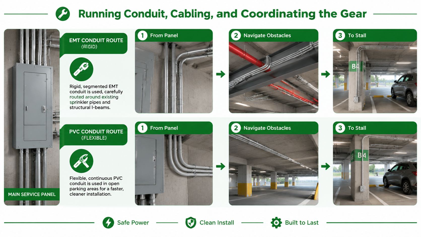
EMT is common in parking garages because it provides a durable, visible raceway and can be routed around sprinkler piping, beams, and other existing systems. It demands careful bending, support, and protection from vehicle impact. PVC can be practical in open areas and underground routes, but it needs appropriate transitions, physical protection, expansion consideration, and careful coordination at exposed equipment.
Don't place conduit where a future sprinkler inspection, garage coating, or structural repair will make access impossible. On post-tensioned decks, a GPR survey should identify tendons before any core drilling begins. A short-looking route that cuts through a structural zone isn't a shortcut. It's a redesign.
Size conductors for the actual route
Level 2 installations commonly use 6 AWG copper on a 50 A circuit, but the final conductor size depends on the charger rating, terminal temperature limitations, ambient conditions, bundling, raceway fill, voltage drop, and adopted code requirements. Long runs require a voltage-drop review so the charger receives stable input and the installation stays within the designer's performance budget.
DC fast chargers can require parallel 250 kcmil feeders, depending on the equipment and service voltage. Runs of 150 to 300 ft can make conductor cost, conduit size, pulling tension, termination space, and voltage drop major design constraints. A charger shown in the far corner of a site may require a different distribution arrangement than the same charger placed beside the electrical room.
Coordinate panels and protection
A dedicated EV panelboard keeps charging circuits identifiable and simplifies maintenance, but it must be sized for the calculated load and future additions. Leaving 25% spare capacity in the panel and distribution arrangement can provide useful expansion room, although spare breaker spaces alone don't guarantee feeder or service headroom.
Match the main breaker and panel AIC rating to the available fault current. Where a step-down transformer supplies the chargers, coordinate the primary and secondary protection and evaluate whether the transformer creates a separately derived system requiring its own grounding and bonding arrangement. The one-line diagram should show these relationships clearly.
Use durable cable management, protect exposed raceways, and keep disconnects accessible. Electrical decisions determine whether a pedestal can land at the preferred stall, whether a wall unit needs a backing structure, and whether a cable crosses a walking path. For related low-voltage communications planning, see low-voltage cabling installation.
Parking Layout, ADA Access, and Fire-Safe Spacing
The parking lot is a layered geometry problem. A layout can fit the charger footprint and still fail because the cable blocks an accessible route, a vehicle swings into a bollard, or firefighters can't reach the equipment without moving parked cars.
Start with the stall and aisle geometry. A commonly used planning dimension is a 9 ft by 18 ft stall, with an additional 5 ft clearance when a charger is mounted between stalls. Those dimensions need to be checked against the governing local parking standard, vehicle mix, turning movements, wheel stops, pedestrian routes, and the actual equipment footprint.
Protect accessible use from the first sketch
For a layout with eight chargers, plan for one van-accessible space per eight chargers, an 8 ft access aisle, a connector and control reach range within 30 inches, and an unobstructed path from the accessible route to the charging position. These requirements come from the project brief's specified planning criteria, but the enforceable requirements can vary by adopted state and local rules, so the AHJ and accessibility professional should review the final plan.
The access aisle isn't extra storage. Don't place bollards, wheel stops, signposts, hose reels, or charging cables where they narrow the maneuvering space. A driver using a mobility device needs to reach the controls, handle the connector, and exit toward the accessible route without crossing a traffic lane unnecessarily.
| Element | Minimum Dimension | Code Reference |
|---|---|---|
| Standard planning stall | 9 ft by 18 ft | Verify local parking standard |
| Clearance for between-stall mounting | 5 ft | Project layout criterion |
| Van-accessible allocation | One space per eight chargers | Project accessibility criterion |
| Accessible access aisle | 8 ft | Project accessibility criterion |
| Connector and control reach | 30 inches | Project accessibility criterion |
Treat fire safety as a layout decision
Recent guidance for EVs parked in enclosed or constrained sites emphasizes maintaining at least 2.5 m of clear, combustible-free area around chargers, using non-combustible floors where possible, preserving firefighting access, and keeping hydrants, ramps, and escape routes clear, as described in the European Observatory guidance on fire safety for parked electric vehicles. That guidance also supports site-specific risk assessment, which may affect whether higher-risk enclosed areas permit only Mode 3 and Mode 4 charging or require visible, reachable emergency stops.
Review the adopted NFPA 88A and IFC Section 1207 requirements with the fire authority. Keep chargers away from combustible storage, protect pedestals with bollards, and avoid placing equipment directly below overhead ventilation intakes or adjacent to transformer vaults unless the design and fire review specifically support it.
Use signage that identifies charging spaces, operating restrictions, and emergency information. Where applicable, coordinate Section 4.3.4 EVCAP signage requirements with the plan reviewer. Concrete islands should be reinforced and finished to withstand carts, vehicles, water, and local maintenance equipment. In snow regions, account for plows. In Southern California retail sites, account for delivery carts, shopping carts, and repeated low-speed vehicle contact.
Utility Coordination, Permits, and Inspections
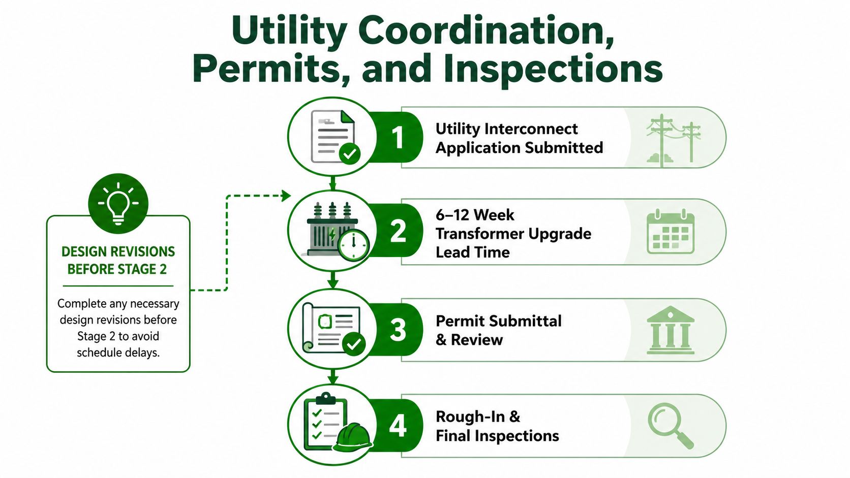
Paperwork should follow the electrical decision sequence. Start with the utility new-load or interconnect review before finalizing equipment procurement, especially when the site may need additional transformer capacity or a service modification.
Put the utility on the critical path early
A service upgrade can trigger a 6 to 12 week transformer upgrade lead time, according to the project planning data, and utility filings may apply when the load crosses 20 kW thresholds under the applicable tariff or Rule 21 process. Confirm the local utility's terminology because EV charging without generation may follow a new-load process, while projects paired with solar, storage, or bidirectional equipment may involve interconnection review.
Submit the one-line diagram, load calculation, service information, charger schedule, site plan, and proposed control strategy as a coordinated package. Design revisions should happen before equipment is ordered or utility engineering is complete. Changing charger output after the utility has based its study on the original load can restart review.
Build the permit set around what inspectors need
California commercial projects may require Title 24 Part 6 compliance documentation, including the EV Cap calculation and the applicable CALGreen Table 5.106.5.3 EVCS tier. Coordinate architectural, electrical, civil, accessibility, and fire documents rather than submitting an electrical plan that leaves the parking and path-of-travel questions unanswered.
Inspectors commonly look for:
- Terminations: Torque marks or documented torque verification on lugs.
- Working space: Clearances complying with NEC 110.26.
- EV labeling: Equipment identification and markings required by NEC Article 625.
- Raceway work: Correct support, grounding, firestopping, burial depth where applicable, and protection from impact.
- Accessibility: Correct striping, signage, routes, aisles, and unobstructed controls.
The utility release and final inspection both need to clear before commissioning and energization. A realistic critical path can reach 8 to 16 weeks, depending on utility review, permitting, equipment availability, and correction cycles. Set the property's occupancy, tenant communication, and revenue expectations against that path instead of promising a construction date based only on the time needed to mount the chargers.
For a commercial checklist covering EV charger installation requirements, align the contractor's field scope with the permit drawings before mobilization.
Commissioning, Maintenance, and Planning for Expansion
Handover isn't a final walkthrough. It's the point where the owner learns whether the installed system performs under the limits established during design.
Commission the complete system
For DC fast charging, perform megohmmeter testing of cable insulation as required by the equipment and commissioning procedure. Verify lug torque, inspect terminations, and use thermal imaging on breaker and feeder connections while the system carries load. Infrared inspection is especially useful for finding a loose or imbalanced termination that looks acceptable when de-energized.
Test GFCI operation in accordance with the equipment listing and UL 2231 requirements. Confirm charger network registration, payment or access controls, time synchronization, alarms, remote reset functions, and backend visibility. Then run the charging system through a controlled peak-load test.
Commissioning record: Document the current-transformer locations, managed-demand setpoints, controller response, charger allocation, and fallback behavior. The next technician should be able to reproduce the test without guessing.
During the first operating week, compare actual load behavior with the load-management settings. Watch for nuisance trips, unexpected derating, communications dropouts, cable damage, and chargers that fail to release capacity when a session ends. A system can pass a visual inspection and still mishandle simultaneous demand.
Maintain equipment before users find the weak point
Set a recurring inspection program that matches the equipment and environment:
- Quarterly field checks: Inspect cables, connectors, holsters, screens, pedestals, bollards, and vehicle-impact damage.
- Annual cabinet service: Clean filters and service fans on liquid-cooled dispensers according to the manufacturer's maintenance instructions.
- Software upkeep: Apply approved firmware and OCPP backend updates after confirming compatibility and rollback procedures.
- Distribution monitoring: Repeat thermography on panels, disconnects, switchgear, and feeder terminations under representative load.
- Documentation control: Record faults, repairs, firmware versions, test results, and warranty claims in the asset file.
Expansion should be designed before the first concrete pour. Reserve conduit stub-outs, spare breaker positions, switchgear bay space, physical charger locations, communications pathways, and transformer headroom. A future addition should require pulling conductors and installing equipment, not demolishing a finished garage or replacing a distribution lineup.
Keep as-builts, one-lines, sequence-of-operation records, commissioning results, utility rate schedules, network credentials, and maintenance history in one controlled binder or digital equivalent. Access Electrical and Lighting provides commercial EV charger installation, including Level 2 network-enabled systems, alongside electrical distribution, low-voltage, testing, and maintenance work for commercial, retail, office, and multifamily properties.
If your property is considering EV charging, have Access Electrical and Lighting assess the service, existing loads, parking layout, conduit routes, accessibility conditions, and expansion requirements before equipment is selected. Visit Access Electrical and Lighting to discuss a site-specific design and installation plan for your Southern California facility.