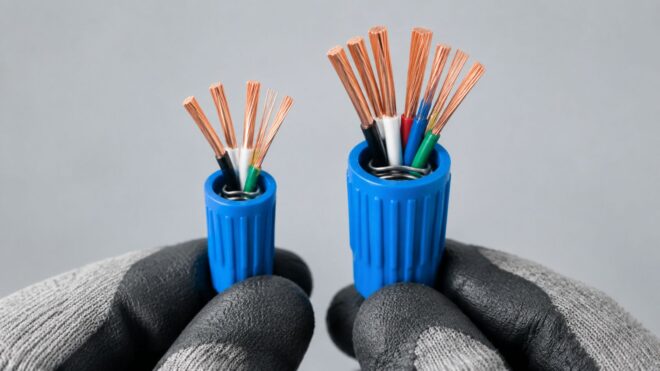
The most popular advice about blue wire nuts capacity is also the least reliable: “Blue means the small connector, so use it for a few light-gauge wires.” That shortcut fails on commercial jobs because blue is used across more than one connector family. A standard 72B-style blue and an IDEAL Wing-Nut 454 “Big Blue” may share a shell color, but their conductor ranges, voltage ratings, and practical applications are very different.
The number that matters isn't the color printed on the shell. It's the part number, conductor combination, conductor material, and listing shown on the manufacturer's chart. Treating color as a specification can leave a splice underfilled, overfilled, or outside the tested combination, which is exactly the kind of detail that creates a failed tug test or an inspection callback. For broader installation and inspection considerations, use this electrical code compliance guide as a companion reference.
Why Blue Wire Nut Capacity Is More Than One Number
Blue identifies a color, not a capacity
A standard blue connector in the 72B class is intended for small conductor combinations, from 2 #22 AWG wires through 3 #16 AWG wires, with a typical 300V rating, according to the 72B product documentation. That makes it a practical choice for fixture wiring, lighting controls, and smaller branch-circuit splices.
The larger Big Blue 454 belongs to a separate capacity class. It covers 14–6 AWG copper conductors and carries a 600 VAC rating, with listed combinations from three #12 conductors to one #6 conductor plus two #8 conductors. The product details are available in the IDEAL 454 product listing. Both shells are blue, but the conductor range, body size, spring design, and application are different.
Practical rule: Select the connector by part number first, then confirm the conductor chart. Shell color is only an identification aid.
Why the shortcut fails in the field
The failure often appears during installation, not at the parts counter. For example, a fixture whip splice with three #14 conductors may tempt an installer to force on a 72B-style connector. If the connection does not hold during the tug test, the problem is not solved by twisting the connector harder. The connector and conductor combination must match the manufacturer's listing.
A Big Blue 454 also needs the correct application. Its larger body is intended for heavier conductors, not for making a very small signal bundle acceptable. The connector choice affects conductor retention, installation quality, and whether the splice can be defended during inspection.
The wire-nut sizing discussion illustrates why color-based selection causes confusion. Different product families use blue for different capacity classes, so the model number and listed gauge combination carry more weight than the shell color.
For commercial work, ask a more precise question than “How many wires fit in a blue wire nut?” Identify the exact connector, conductor gauges, conductor type, and listed application. For broader installation and inspection requirements, consult this electrical code compliance guide.
The Standard Small Blue Connector Explained
The small blue connector on commercial lighting benches is not a universal “blue wire nut.” It usually refers to an IDEAL 72B style or an equivalent product, and its capacity depends on the exact part number and combination chart. The specification table above provides the working range. Use that table as a starting point, then verify the markings on the connector package.
The listing covers more than a color and a plastic shell. UL 486C / CSA C22.2 No. 188 compliance identifies a twist-on wire connector evaluated for the listed conductor combinations and installation conditions. The connector's 105°C, or 221°F, flame-retardant thermoplastic shell describes the housing material and temperature class. It does not establish circuit ampacity or permit a splice outside the listed combination.
Those limits belong to different parts of the installation. A 300V connector does not set the allowable current for a branch circuit. The shell temperature rating does not override conductor insulation, terminal, enclosure, or code requirements. Treat the rating block as evidence of the connector's tested use, not as a substitute for the wiring rules.
Reading the label correctly
Start with the model number, then read the combination column that matches the conductors in hand.
- Check the smallest permitted combination. A connector that is too large may not compress the conductors firmly enough.
- Check the largest permitted combination. The shell and spring must contain the conductor volume without forcing.
- Separate solid and stranded entries. If the chart provides separate columns, use the correct one. A solid-wire allowance does not automatically cover the same stranded combination.
- Confirm conductor material. Small blue connectors are generally intended for copper-to-copper splices unless the product carries an aluminum-compatible marking.
| Specification | Typical value | Notes |
|---|---|---|
| Connector class | 72B-style small blue | Verify the actual manufacturer and part number |
| Voltage rating | 300V | Applies to the listed connector class and installation conditions |
| Conductor range | 2 #22 AWG to 3 #16 AWG | Exact combinations depend on the published chart |
| Shell rating | 105°C, 221°F | Flame-retardant thermoplastic shell |
| Listing | UL 486C and CSA C22.2 No. 188 | Confirm the marking on the product being installed |
| Conductor material | Copper-to-copper | Do not assume aluminum compatibility without an AL/CU marking |
The practical limit is the exact row, not the headline range. If the chart lists the combination, follow it as printed. If it does not, choose a connector with a listed capacity rather than forcing the splice and relying on extra twisting.
Small Blue vs Big Blue Side by Side
Blue is a color code, not a capacity rating. A 72B-style small blue connector and a Big Blue 454 belong to different connector families. The small model handles fine conductors and compact bundles. The 454 uses a wider shell and heavier spring for larger copper combinations.
The IDEAL Wing-Nut 454 specifications show why the larger model cannot be treated as an oversized small blue. Its body, spring, and listed combinations are intended for a different range of splice work. The relevant question is not which connector looks roomier. It is whether the exact conductor mix appears on that model's chart.
| Attribute | Small Blue, 72B style | Big Blue, 454 style |
|---|---|---|
| Typical use | Fixture, lighting, and control splices | Larger branch-circuit and commercial splices |
| Body and spring | Compact shell for smaller bundles | Wider shell with a heavier spring |
| Example combination | Fine-wire entries listed by the 72B chart | Three #12 conductors, or one #6 plus two #8 conductors |
| Installation check | Follow the model's strip-length and combination instructions | Follow the 454 chart, strip requirements, and conductor mix |
| Selection basis | Exact 72B-style chart | Exact 454 chart |
Where each connector works
A small blue fits a compact fixture-lead splice when the conductors match its published entries. It is easier to handle in a crowded box and does not take up space intended for larger conductors. Its smaller body still requires enough conductor length for the spring to engage correctly.
The Big Blue suits a larger branch-circuit bundle only when the 454 chart permits that combination. Its wider shell gives the conductors room, while the heavier spring provides the mechanical grip expected for that connector family. Shell size alone does not approve a splice.
A larger connector is not a universal upgrade. On a two-conductor #18 signal run, a Big Blue may not engage the bundle firmly enough. On the other hand, forcing a small blue onto a large mixed-gauge lighting or power splice can overfill the shell and reduce retention.
Procurement labels matter on mixed commercial jobs. A bin marked only “blue” leaves too much room for error. Identify the manufacturer, model, and connector family, then verify the conductor combination against the printed chart before installation. Color helps locate the part. The model number determines whether it passes inspection.
How Conductor Mix Sets Real Capacity
A wire-nut chart is not a simple wire-count calculator. Conductor gauge and count work together, and an approved combination can change sharply as the bundle grows. The larger Big Blue family is a useful example. Its chart includes both smaller bundles and large mixed-gauge combinations, but those entries are tested combinations, not endpoints for guesswork.
A bundle of large conductors consumes space and changes spring engagement differently from a bundle of smaller conductors. Each added conductor increases bundle diameter and changes how the spring bears against the copper. The connector's color does not account for those differences.
Read combinations as tested entries
Use the manufacturer's chart as a list of approved combinations. For example, two #10 conductors plus one #12 may look close in volume to another listed three-conductor splice, yet that does not authorize the mixture. The spring may engage the conductors differently, and the manufacturer may not have evaluated that exact arrangement.
| Connector | Combination examples | Notes |
|---|---|---|
| Small blue, 72B style | 2 #22 AWG, 3 #16 AWG, and other listed combinations | Use the exact 72B-style chart for the applicable conductor type |
| Big Blue, 454 style | Listed small and mixed-gauge combinations, including the chart's large-conductor entries | Confirm the exact 454 row, strip requirements, and conductor mix before installation |
A listed AWG range still requires careful reading. If the chart gives a range or several conductor categories, treat each entry according to its stated combination. Do not assume that any mixture within the visible range is acceptable.
A connector's maximum count is not a target. It is the outer boundary of a tested combination.
Mixed-gauge work deserves the same caution. Two larger conductors and a smaller tap can create a different bundle shape from three conductors of one gauge. That affects both mechanical grip and the space available inside the shell. If the exact mixture does not appear in the chart, select a connector with a listed combination or use another approved connection method.
An unlisted splice creates a compliance problem as well as a mechanical one. The spring may not achieve the intended contact pressure, and the connection may fall outside the connector's UL or CSA evaluation. For a loose or intermittent joint that has already been installed, use qualified electrical troubleshooting services instead of trying to conceal the fault with tape.
Solid, Stranded, and Temperature Considerations
Solid and stranded copper do not behave identically inside a twist-on connector. Solid conductors give the spring a consistent surface. Stranded conductors can compress, spread, or unravel during installation, changing the contact geometry even when the nominal AWG marking matches.
Read the manufacturer's solid and stranded columns separately whenever both are provided. A connector that grips a compact solid bundle may not perform the same way on a flexible fixture lead or control cable. If strands remain outside the spring, or the bundle will not seat evenly, remove and rework the splice. Do not rely on tightening the cap to correct a poorly formed connection.
Material compatibility comes first
A small blue connector is not automatically approved for aluminum or copper-clad aluminum. Look for an explicit AL/CU marking or manufacturer instruction that covers the conductor material. Shell color alone says nothing about mixed-metal compatibility.
Identify the conductor material before selecting the connector, then verify the exact product listing. This check matters during commercial remodels, where existing branch wiring and new fixture leads may use different conductor constructions. A copper-rated connector is not a substitute for a connector listed for the actual metals being joined.
Temperature ratings have limits
A 105°C shell rating applies to the connector housing. It does not set the allowable operating temperature for the conductors, terminals, enclosure, or complete splice. Check the wire insulation rating, equipment terminals, ambient temperature, enclosure conditions, and applicable derating rules together.
Ambient conditions can change the acceptable connector choice. A splice above rooftop HVAC equipment, inside a crowded mechanical room, or in a raceway exposed to sunlight may run hotter than one in a quiet indoor junction box. Derating can also reduce the usable ampacity of the conductors, even when the connector's housing rating appears adequate.
Moisture and enclosure conditions add another constraint. A connector may have the right temperature marking yet remain unsuitable if the conductor material, enclosure listing, moisture protection, or circuit conditions do not match the installation.
The shell temperature marking is one input. Evaluate the complete wiring environment before approving the connector.
Where Blue Wire Nuts Actually Show Up in Commercial Work
Commercial electricians encounter blue connectors most often in compact lighting and control work, but the right model depends on the splice in front of them. Packaging examples tend to show a clean, uniform bundle. Jobsite wiring is less cooperative, with fixture whips, tap conductors, stranded leads, and control wiring arriving together in the same box.
Fixture whips and lighting splices
A small blue connector can be appropriate when the fixture conductors fall within the 72B-style chart. A typical task might involve a small line or neutral lead paired with another fine conductor, but the installer still needs to identify the gauge, conductor type, and number of wires before choosing the connector.
A third conductor changes the decision. The combination may remain acceptable if it appears on the chart, or it may require a different model if the gauge or conductor type pushes the bundle beyond the listed range. The shell color doesn't resolve that question.
Lighting controls and mixed conductors
Control work creates a common trap. A lighting-control box may contain solid branch-circuit conductors alongside stranded fixture or control leads. A blue connector selected for one part of the wiring may not be listed for the complete mixed bundle.
A 0–10V control pair and line-voltage conductors also shouldn't be combined casually simply because the wire bundle is physically small. Circuit function, insulation, separation, conductor type, and connector listing all matter. If the splice doesn't appear as a tested combination, use a connector or terminal system specifically suited to that wiring arrangement.
HVAC control wiring
Low-voltage HVAC control wiring often uses small conductors and compact bundles, which can make a small blue connector attractive. But a 24V control circuit still needs a mechanically secure connection, especially around rooftop equipment where vibration, heat, and service access can affect long-term reliability.
A connector used inside or near HVAC equipment must match the environmental and temperature requirements of the equipment. The fact that the circuit voltage is low doesn't make an unlisted or loose splice acceptable.
Inspection-sensitive installations
Commercial projects governed by project specifications, local requirements, or California energy-code documentation demand more than a color match. Lighting-control installations under Title 24 need listed components, documented testing, and an installation that can be traced back to the approved design and product data.
A red tag rarely comes from the word “blue.” It comes from an unverified model, an unlisted combination, or workmanship that doesn't survive inspection.
Keep the product documentation available for the connector family being installed. For projects requiring formal review, commercial electrical inspection support can help identify splice, labeling, and documentation issues before they become closeout problems.
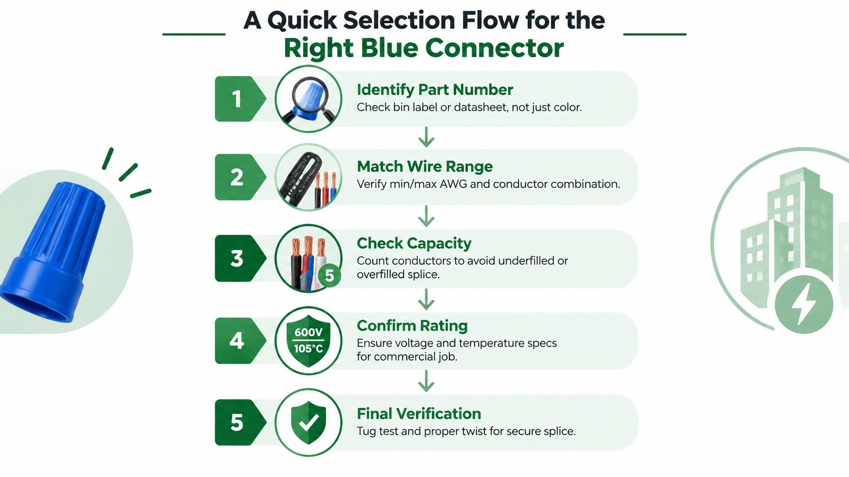
A Quick Selection Flow for the Right Blue Connector
A blue shell is not a capacity specification. Selection starts with the connector's part number, then works through the actual conductor bundle. The same checks should apply in a ceiling box, lighting-control enclosure, or mechanical-room junction box.
Five checks before installation
Identify the part number. Read the bin label, package, or datasheet. Confirm whether the connector is a small 72B-style blue or a 454-style Big Blue. Color is only a starting clue.
Record every conductor. List the AWG size, quantity, material, and whether each conductor is solid or stranded. A mixed bundle cannot be reduced to one nominal gauge.
Match the combination chart. Find the exact row for the bundle. Check the lower limit as well as the upper limit, since an underfilled connector may not compress the spring correctly.
Confirm the application rating. Verify voltage, shell temperature, conductor material, and listing. A 300V small blue and a 600V Big Blue are different products, even though both are blue.
Install and verify. Follow the manufacturer's strip-length and installation instructions. Perform a gentle individual tug test, then inspect for exposed copper, damaged insulation, a cracked shell, or a connector forced onto the bundle.
Make the process inspection-ready
Keep the applicable manufacturer chart in the service vehicle or project file. Color rules fail when brands, connector families, and mixed-gauge splices change, so the chart needs to stay with the crew.
For a practical check, consider a ceiling box containing two #12 solid branch conductors and one #16 stranded fixture lead. First, identify the connector family. Next, record the two conductor sizes, the stranded lead, and the full count. Then locate that exact mixed combination in the manufacturer's chart, rather than treating the bundle as three #12 conductors.
After the chart confirms the combination, verify the voltage, temperature, material, and listing for that connector. Strip each conductor to the specified length, install the connector without forcing it, and tug each conductor individually. Look for exposed copper or insulation caught under the spring.
For a small 72B-style connector, confirm that the fine-wire bundle falls within its published range. For a Big Blue 454, check the larger conductor combination directly against the 454 chart and product information already identified earlier.
A tug test cannot approve an unlisted combination. It checks workmanship after the selection is correct. It does not replace the product chart, listing, or project requirements.
For commercial work, record the connector model when as-built documentation is required. That detail lets the next technician identify the installed product without guessing from a faded shell or unfamiliar package.
Access Electrical and Lighting can help commercial property teams with lighting splices, controls, troubleshooting, infrared inspections, and inspection-ready electrical work across Southern California. Visit Access Electrical and Lighting to request support for connector selection, repair, testing, or a broader commercial electrical project.