
A property manager often discovers an exit sign problem at the worst possible time. The fixture above the corridor door looks bright, the cover is clean, and the normal lighting circuit works. Then someone opens the panel during an outage drill, the building goes dark, and the sign either fails to transfer, loses useful brightness, or points occupants toward a route they can't see.
That's why exit sign installation isn't just a mounting task. It involves placement, sightlines, circuit integrity, emergency transfer, illumination, commissioning, and records that prove the system remains dependable. In Southern California commercial properties, a sign can look acceptable during a walk-through and still expose the owner to avoidable inspection and life-safety problems.
Why Exit Sign Installation Demands More Than a Ladder and a Drill
A property manager had a tenant improvement completed before a scheduled emergency drill. Every exit sign appeared illuminated during the final walk-through. The housings were level, the lettering was visible, and nothing looked obviously wrong.
During the drill, the normal lighting was interrupted. One sign stayed dark because its battery had never been properly verified. Another illuminated, but an obstruction near the corridor corner made it difficult to see from the approach path. The installation had passed a casual visual check, but the emergency condition exposed the gaps.
That scenario is common enough to deserve a different workflow. Normal power proves only that the fixture receives power under normal conditions. It doesn't prove that the battery is charged, the transfer circuit operates, the emergency source carries the load, or the sign remains readable when the building loses power.

The hidden failure points
The visible fixture is only one part of the system. A reliable installation also depends on:
- Correct location: Occupants need to identify the sign from the normal exit-access path, not only from directly below it.
- Uninterrupted power: A wall switch, mislabeled breaker, or incorrect circuit connection can disable the sign during routine maintenance or an emergency.
- Emergency transfer: Battery units and inverter systems must transfer automatically when normal power drops.
- Sustained operation: The emergency source must continue supporting the sign for the required duration.
- Verification records: Test results give the owner, inspector, and maintenance team evidence that the system was checked under the condition that matters.
Field observation: The most dangerous exit sign is often the one that looks finished. A clean faceplate can hide a dead battery, a failed relay, or a circuit that someone can switch off.
A code-driven placement review from the OCWR exit and related signs guidance emphasizes visibility, viewing distance, and mounting height. The same practical principle applies to commissioning. Installers should verify the sign in normal operation, then deliberately test the outage condition before closeout.
The liability issue grows when nobody owns the next step. The electrician may assume the facility team will test the battery. The facility team may assume the original installer commissioned it. Months later, a failed unit has no clear service history. Proper exit sign installation closes that gap by treating the fixture as a life-safety device, not ordinary finish work.
Planning Placement and Mounting Before You Pick Up a Tool
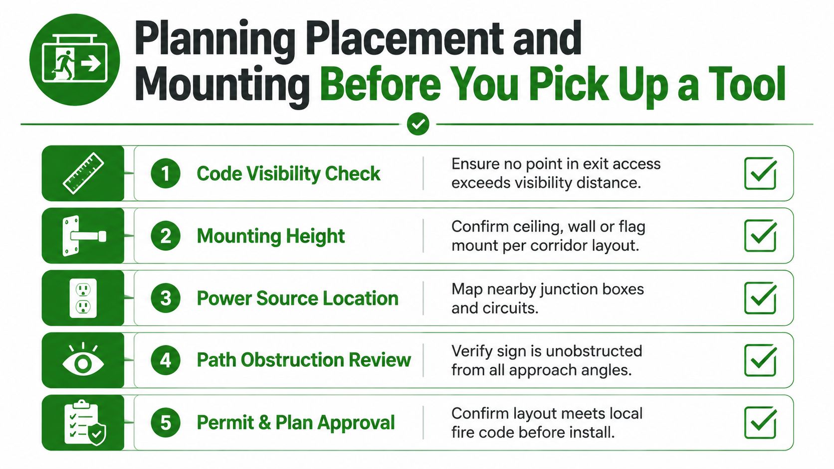
Begin the placement review at the egress route rather than at the nearest junction box. Walk from the areas occupants use, follow each exit-access corridor, and mark every point where the direction of travel becomes unclear. An exit sign should be readily visible from any direction of exit access where the path isn't obvious. Keep corridor locations within the sign's rated viewing distance or 30 m, 100 ft, whichever is less, following the OCWR installation guidance.
Walk the route from the occupant's position
A plan view can hide problems that are obvious at eye level. Stand where occupants normally approach, look toward the proposed sign, and repeat the check from both directions when the corridor serves more than one movement path.
Check the conditions that often change after drawings are finished:
- Mechanical obstructions: HVAC ducts, soffits, cable trays, and sprinkler piping can interrupt the sightline.
- Architectural features: Columns, ceiling drops, and corridor offsets can hide a sign until someone has passed the decision point.
- Finished signage: Tenant graphics, room identifiers, banners, and decorative elements can compete with or cover the exit face.
- Branching corridors: A sign above the final door may not guide occupants who must choose a direction earlier.
If someone must guess where to turn, the layout needs another visible indication or a better sign position. A fixture can pass a visual walkthrough and still fail during an outage if its face is hidden from the actual approach path.
Set the mounting height and orientation
Per the guidance cited above, the bottom of the sign should be installed at least 80 inches above the finished floor. Confirm that dimension after flooring, ceiling, and trim conditions are established. Remodels commonly leave an existing box at an elevation that no longer matches the finished space.
Choose wall, ceiling, or flag mounting from the corridor geometry. A single-face sign may serve a door approached from one direction. Where occupants approach perpendicular to the wall, a double-face configuration or projecting mount may provide the needed view. The product listing and approved plans control the final assembly, including the arrow configuration and mounting hardware.
Record decisions before rough-in
Before rough-in, mark the fixture tag, mounting surface, power source, and expected viewing direction on the electrical plan. Photograph concealed junction boxes before ceilings close. Label the supplying circuit at the panel and the local box so a later service technician can identify the life-safety connection without opening finished surfaces.
These records also expose hidden compliance gaps during closeout. Years later, a technician may find a sign that fails to transfer during an outage and have no reliable way to separate a housing fault from a junction-box issue or an upstream emergency-source problem. A placement record, photo, and circuit label make that diagnosis faster and give the inspector a clear installation trail.
Wiring Hardwired and Battery Backup Exit Signs
The wiring method depends on the emergency architecture selected for the property. A self-contained unit normally receives normal building power and uses an internal battery when that power fails. A central inverter arrangement may supply emergency power to multiple fixtures through a dedicated system. Those approaches aren't interchangeable, and the wiring diagram supplied with the listed equipment should govern the connections.
Hardwired connections
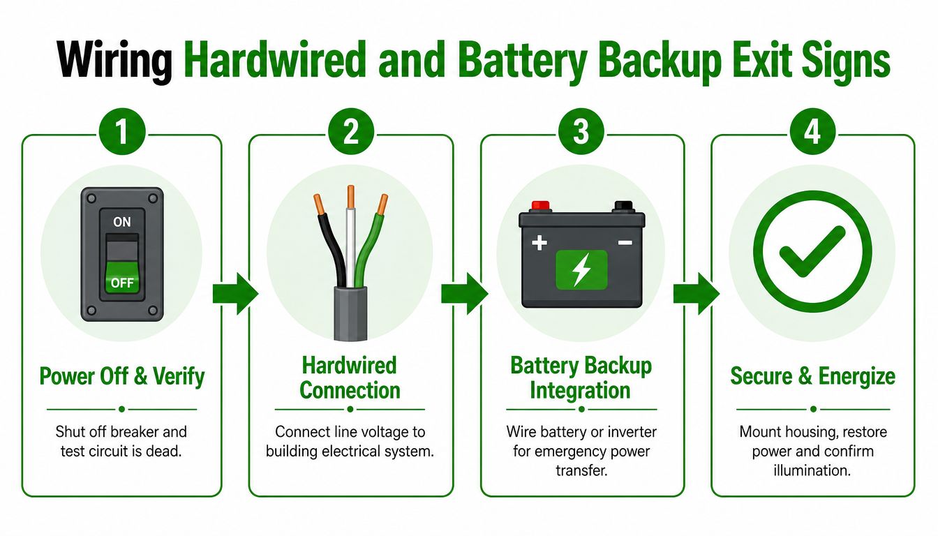
For a standard hardwired unit, the installer first confirms the voltage and identifies an unswitched source intended to remain energized. The line, neutral, and equipment grounding conductor are connected according to the fixture instructions and the applicable electrical design.
The sign shouldn't be placed on a circuit that building occupants can casually turn off. At the panel, identify the circuit clearly. At the junction box, use durable labeling that tells the maintenance technician the circuit supports life-safety equipment.
During new construction, coordinate the box location with the final mounting method. A wall box centered over a door may not work for a flag-mounted sign, and a ceiling box can create a poor sightline if the corridor changes direction below it.
Battery and inverter arrangements
A battery backup unit normally charges while normal power is available, then transfers the sign to its emergency source when normal power is interrupted. That transfer may occur inside the fixture through an electronic control or relay. The installer must confirm that the normal-power input and emergency components are connected as the manufacturer shows.
Central inverter systems require more coordination. The emergency branch, transfer equipment, circuit identification, and load coverage must match the approved design. A sign connected to the wrong branch may illuminate during a local test while still failing when the intended emergency source drops.
For product selection and installation planning, review emergency exit lights with battery backup alongside the fixture documentation and project drawings.
Retrofit checks that prevent repeat visits
Retrofits often inherit junction boxes, conductors, and labels from an earlier installation. Open the box, verify the actual conductors, and test the source rather than assuming the old labeling is correct. If a wall switch controls the existing sign, correct the control arrangement before installing the new housing.
Use the conductor size and overcurrent protection required by the design and equipment instructions. Don't choose wire solely because it fits the terminal. After termination, secure the conductors so the cover closes without pinching insulation, then restore power and confirm both normal illumination and emergency transfer.
Meeting NFPA 101 and California Title 24 Requirements
A sign can pass a daytime walk-through and still fail when the building loses normal power. Compliance requires two checks: the exit marking must remain readable, and its emergency power and illumination must perform under outage conditions.
The NFPA 101 requirements summary identifies at least 5 foot-candles, or 54 lux, at the illuminated surface for externally illuminated exit signs. It also summarizes the commonly referenced 90-minute emergency-duration requirement during power loss. Confirm the adopted edition, approved plans, and local amendments with the authority having jurisdiction before treating those values as the project's final acceptance criteria.
Internally illuminated LED signs contain their own light source, so the lettering, battery system, transfer function, and emergency indicator all need verification. Externally illuminated signs add a separate failure point. The sign face may look intact while the supplying fixture is weak, misdirected, switched off, or connected to the wrong emergency source.
Comparison of the main compliance questions
| Requirement | NFPA 101 | California Title 24 |
|---|---|---|
| Sign visibility | Exit and egress markings must be illuminated and readable. | Confirm the adopted California requirements, approved plans, and local enforcement criteria. |
| External illumination | At least 5 foot-candles, 54 lux, at the illuminated surface, as summarized in the cited NFPA reference. | Coordinate emergency-lighting design and verification with applicable California energy and building requirements. |
| Emergency operation | The cited NFPA material summarizes 90-minute operation during power loss. | Record the required emergency performance and project testing. |
| Closeout evidence | Keep inspection and functional test results. | Maintain the Title 24 documentation, testing, and certification required for the project scope. |
Use this California Title 24 requirements resource to organize California-specific documentation, then follow the approved plans and the inspector's direction. A resource page does not replace the adopted code or the AHJ's interpretation.
Measure instead of judging by eye
Brightness by eye is not a compliance test. Where the design calls for external illumination, use a calibrated light meter at the sign surface and record whether the fixture was operating from normal or emergency power. For internally illuminated equipment, verify the listed product, lettering visibility, indicator status, transfer behavior, and emergency operation against the manufacturer's instructions and project requirements.
A useful closeout file contains the submittal, fixture model, wiring diagram, meter readings, functional test results, and correction records. It should show what was installed, how it was powered, and what happened when normal power was removed. That record exposes hidden gaps that a visual inspection can miss and gives the inspector a clear basis for reviewing the installation.
Commissioning and Testing Before the Inspector Arrives
A sign can look perfect during a walkthrough and fail the moment normal power drops. Commissioning must reproduce that failure condition under a controlled procedure, then document the result. The 90-minute duration requirement described in the compliance section above applies to the emergency operation test.
Use a controlled test sequence
Start with normal-power inspection. Confirm full illumination, secure mounting, correct arrows or directional elements, and a clear view from the approved approach. Check circuit identification before operating the test switch, breaker, or transfer equipment.
Interrupt normal power only through the approved method. Do not pull random conductors or open energized equipment to simulate an outage. Observe automatic transfer, emergency indicator behavior, and sign visibility throughout the changeover.
A practical commissioning sequence includes:
- Normal operation: Check illumination, face condition, mounting, and circuit identification.
- Transfer response: Remove normal power through the approved test method and observe the emergency source.
- Illumination verification: Measure the relevant illuminated surface when the design requires a meter reading.
- Duration testing: Run the required emergency-duration test described in the compliance section above.
- Closeout records: Log the fixture location, test method, result, corrective action, and responsible technician.
The sequence should follow the project requirements and the manufacturer's instructions. A test switch that proves transfer does not, by itself, prove sustained emergency performance.
Treat a failed test as a diagnostic event
If a sign drops out during transfer, check the normal input, battery connection, charger status, transfer relay, and emergency circuit. If it dims substantially, inspect battery condition, terminal connections, internal electronics, and the emergency source under load.
After a failed test, resist the urge to reset the unit and move on. Tag the fixture, record the failure, correct the cause, and repeat the relevant test. For larger properties, schedule testing during low occupancy and coordinate with security, tenants, and building operations so a planned outage is understood.
A written procedure and consistent log make emergency lighting testing repeatable across buildings. Keep the test method, readings where required, observed transfer response, and corrective work together. That evidence exposes gaps a visual inspection can miss and gives the inspector a clear record of how the system was verified.
Building a Maintenance and Documentation Program
Installation ends when the maintenance obligation begins. Batteries age, connections loosen, charging components fail, and emergency electronics can deteriorate while the sign continues to look normal during everyday operation.
Property managers should assign ownership for inspections and keep the asset list specific. “Second-floor corridor” isn't enough when a building has several branches. Use a fixture identifier tied to a floor plan, panel designation, or room reference so a technician can find the exact unit without guesswork.
Build the log around the fixture
A useful maintenance record includes:
- Asset location: Building, floor, corridor, door, and fixture identifier.
- Power arrangement: Normal circuit, emergency circuit or inverter source, and test method.
- Visual condition: Face, housing, mounting hardware, obstruction, and directional indication.
- Functional result: Normal illumination, transfer response, emergency illumination, and duration test result.
- Corrective work: Battery, relay, wiring, housing, or source repair.
- Closeout evidence: Technician, date, measurements where required, and follow-up status.
The log should show failed tests as clearly as passing tests. Erasing a failed result hides the maintenance history and makes it harder to identify recurring problems. A corrected failure followed by a documented retest is much more useful.
Use walkthroughs to find physical changes
A tenant improvement can add a cabinet, sign, partition, or decorative element that blocks a once-clear sightline. Include exit signs in routine facility walks, not just electrical service visits.
Check for dirt on the face, loose brackets, cracked housings, status indicators, unusual buzzing, and signs that someone has painted or covered the fixture. Verify that panel schedules and field labels still agree, especially after tenant work.
Maintenance rule: A test record should let another technician understand what happened without calling the person who performed the work.
Decide when internal staff need support
In-house teams can often handle visual checks and straightforward reporting if they have a defined procedure. Electrical diagnosis, circuit modifications, battery replacement inside listed equipment, inverter troubleshooting, and Title 24 closeout work require appropriate training and authorization.
For multi-property portfolios, standardize the form and naming convention, then review open failures by building. A manager should be able to identify which units are out of service, what temporary protection is in place, and when the permanent repair is scheduled.
When to Call a Licensed Commercial Electrical Contractor
A simple fixture replacement may look manageable, but commercial exit sign work becomes more involved when the existing circuit is unknown, the emergency source is centralized, or the approved plans require coordinated testing and documentation. In those situations, a licensed California C-10 contractor can evaluate the line-voltage work, emergency transfer arrangement, mounting conditions, and closeout requirements as one scope.
Bring in a professional when the project includes:
- Multi-circuit retrofits: Existing signs may draw from different panels or emergency branches.
- Central inverter systems: The contractor must coordinate source capacity, transfer behavior, and circuit identification.
- Title 24 documentation: Testing and certification need to align with the project record.
- Repeated outage failures: A replacement sign won't solve an upstream battery, relay, or circuit problem.
- Difficult access: High ceilings, occupied corridors, and restricted commercial areas require safe planning and suitable equipment.
Compare proposals by more than fixture price. Ask whether the contractor includes sightline verification, circuit labeling, emergency transfer testing, duration testing, measured illumination where applicable, correction work, and a final service report.
Property managers can retain routine visual checks in-house, but complex installations and recurring failures deserve professional oversight. The cost of a documented inspection is easier to defend than an undocumented assumption that the sign will work when normal power disappears.
Access Electrical and Lighting installs, tests, maintains, and repairs commercial exit signs, emergency lighting, and battery backup systems across Southern California. Visit Access Electrical and Lighting to request a site review and build a documented installation or maintenance plan for your property.