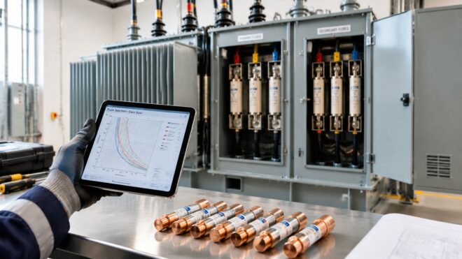
You're standing in front of a commercial transformer, replacement fuses in hand, while someone asks whether the primary should be sized from the nameplate current, the NEC percentage, or the fuse that stopped nuisance trips last month. The calculation is straightforward. The difficult part is choosing a device that satisfies the code limit, survives magnetizing inrush, and coordinates with the secondary and downstream equipment.
Good fuse sizing for transformers starts with accurate transformer data and ends with a documented coordination decision. A percentage calculation alone can produce a compliant answer that still causes an outage when the transformer is energized or when a modern load, such as an EV charger or VFD, changes the current profile.
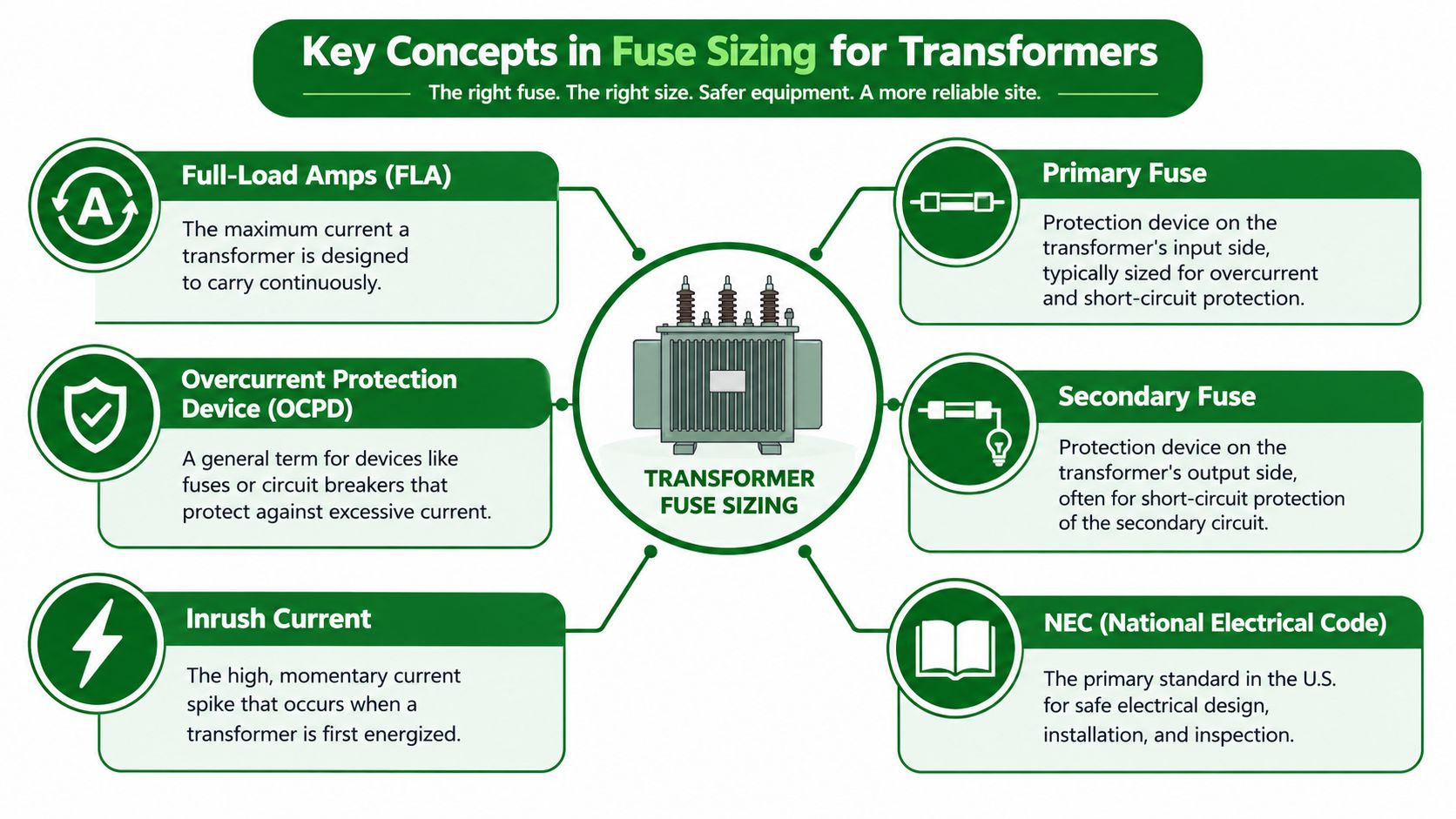
Key Concepts in Fuse Sizing for Transformers
A transformer can pass a nameplate-current check and still trip the moment it is energized. In a commercial installation, fuse selection has to account for the transformer's load current, protection arrangement, magnetizing inrush, and the fault-clearing needs of connected equipment. These decisions connect NEC limits with the time-current behavior of real fuses.
Full-load current, or FLA, is the current a transformer is designed to carry continuously at its rated kVA and voltage. The primary is the input side. The secondary is the output side serving panels, controls, and branch circuits.
The primary fuse protects the transformer and supply conductors on the input side. A secondary fuse protects the output conductors and downstream equipment. Both are overcurrent protection devices, or OCPDs, but they can have different coordination duties.
Why the primary and secondary percentages differ
For transformers rated 1,000 V and under, NEC-based guidance commonly limits the primary fuse to 125% of transformer full-load current when the fuse is the only protection. It permits up to 250% when the secondary is separately protected, subject to the applicable installation conditions. These figures are maximum permitted values, not automatic targets. The NEC transformer fuse sizing guide provides the related sizing framework.
A separately protected secondary can clear many downstream overloads and faults without requiring the primary fuse to respond immediately. That arrangement may allow a primary device with enough time-delay behavior to ride through transformer energization while the secondary device protects its conductors and loads.
For small primary currents, the permitted ceiling changes. NEC-based guidance identifies 167% for primary currents from 2 to 9 A and 300% below 2 A, subject to rounding to the next standard fuse size in the NEMA series. Common standard ratings include 15 A, 20 A, 25 A, 30 A, 35 A, 40 A, 45 A, 50 A, 60 A, 70 A, 80 A, 90 A, 100 A, 110 A, 125 A, 150 A, 175 A, 200 A, 225 A, 250 A, 300 A, 350 A, 400 A, 450 A, and 500 A, with higher ratings available in the series.
A field example
On a 75 kVA installation, the primary FLA calculation may be correct while the selected device still performs poorly. Check the secondary protection, transformer impedance, available fault current, fuse time-current curve, and expected inrush before approving the replacement. A primary-only arrangement generally leaves less room for oversizing than a primary-and-secondary arrangement.
Practical rule: Treat the NEC percentage as a ceiling. The final fuse must also match the manufacturer's instructions, conductor protection, interrupting rating, inrush response, and coordination requirements.
For broader installation decisions, review this guidance on electrical code compliance. Code compliance establishes the boundary. Fuse coordination determines whether the installation operates reliably.
Gathering Transformer Data and Specifications
The fuse calculation is only as good as the nameplate information behind it. Before selecting a replacement, photograph the transformer nameplate, record the kVA rating, and identify the primary and secondary voltages exactly as marked. Don't rely on a panel schedule that may describe an earlier transformer or a different tap arrangement.
Start at the nameplate
Record these items before opening a calculation sheet:
- Transformer rating: Capture the kVA value and confirm whether the unit is single-phase or three-phase.
- Primary voltage: Note the nominal voltage, available taps, and the actual connection in the enclosure.
- Secondary voltage: Record the output voltage and whether the conductors feed a panel, controls, or a dedicated piece of equipment.
- Impedance and temperature information: Preserve all manufacturer markings that may affect fault calculations, loading, or thermal performance.
- Existing protection: Identify fuse class, voltage rating, ampere rating, time-delay characteristics, and whether protection exists on both sides.
Use a properly rated meter and an approved test procedure to verify the supply and secondary readings. A voltage that differs from the expected nameplate connection may indicate a tap issue, an upstream supply problem, or a measurement error. De-energize and establish the required electrical safety boundaries before inspecting or testing inside the panel.
Document the actual load
The connected load often explains a nuisance trip better than the transformer nameplate does. List downstream equipment such as EV chargers, VFD-driven HVAC systems, LED drivers, electronic controls, and power supplies, then identify which loads operate at startup and which remain energized continuously.
That inventory matters because modern commercial equipment can produce starting transients, nonlinear current, and operating conditions that a simple steady-state calculation won't reveal. The goal isn't to guess a larger fuse. The goal is to understand whether the transformer is being loaded, energized, or faulted in a way the original selection didn't anticipate.
A useful site record includes the date, ambient conditions, measured voltages, measured load current, transformer temperature observations, and the reason for any fuse replacement. Keep the calculation with the equipment documentation, and use the guidance on calculating transformer size when the existing transformer rating or connected load needs to be reassessed.
Primary Fuse Sizing Calculations
A transformer can pass a steady-state calculation and still nuisance-trip when energized. Start with the primary full-load current, then check the fuse against conductors, equipment, and expected inrush.
For a single-phase transformer, calculate:
Primary FLA = (kVA × 1,000) ÷ primary voltage
For a three-phase transformer, the calculation includes the three-phase factor. Use the manufacturer's data and applicable installation requirements rather than applying the single-phase formula to a three-phase unit.
Apply the primary protection limit
For a transformer under 1,000 V, NEC-based guidance commonly uses 125% of primary full-load current when primary protection is the only protection, or up to 250% when secondary fuses are installed. Confirm the permitted percentage and standard fuse rating for the specific installation.
Consider a 50 kVA, 480 V single-phase transformer:
- Calculate primary FLA:
(50 × 1,000) ÷ 480 = 104.17 A - With primary-only protection, apply 125%:
104.17 × 1.25 = 130.21 A - Move to the next standard fuse rating in the applicable series:
150 A
This calculation establishes a maximum-style value, not an automatic installation choice. The selected fuse must protect the conductors, fit the holder, meet voltage and interrupting requirements, and tolerate expected transformer energization. Check the manufacturer's time-current information when inrush is likely to overlap the fuse curve.
With separately protected secondary conductors, the primary ceiling may be calculated at 250%:
104.17 × 2.50 = 260.42 A
The next standard rating is 300 A, yet that device may be unsuitable where conductor ampacity, transformer instructions, downstream coordination, or available fault current calls for a lower rating. A larger fuse may reduce nuisance openings while delaying fault clearing.
For related current conversions, use this watts-to-amps calculation guide. Keep watts, volt-amperes, and transformer kVA distinct before entering values into the fuse calculation.
The right answer is the smallest standard device that clears the required fault and remains stable during normal energization.
Secondary Fuse Sizing Calculations
Secondary protection begins with the output side's full-load current. For a single-phase transformer, calculate:
Secondary FLA = (kVA × 1,000) ÷ secondary voltage
A 75 kVA, 208 V single-phase transformer produces:
(75 × 1,000) ÷ 208 = 360.58 A
Where the applicable secondary protection rule limits the fuse to 125% of secondary full-load current, the calculation becomes:
360.58 × 1.25 = 450.73 A
The next standard fuse rating is 500 A, subject to the installation's conductor, equipment, and manufacturer requirements. This example shows why the calculated value must be checked against the actual secondary conductors and distribution equipment. A standard fuse rating that rounds upward may exceed what the wiring method or equipment is designed to accept.
Coordination matters more than the arithmetic
Independent manufacturer guidance describes secondary fuse sizing around the 125% full-load-current limit, while emphasizing verification of coordination downstream of the transformer to reduce nuisance trips, as explained in this Mersen low-voltage transformer application information.
Review the downstream panel main, feeder devices, and branch fuses together. The secondary fuse should not open unnecessarily for a fault that a branch device can clear. Conversely, a branch device shouldn't be selected so high that the transformer secondary fuse becomes the first device to operate for every downstream event.
A practical coordination review
For a mixed-use commercial property, identify the largest branch loads and any equipment with electronic power conversion. EV charging equipment, VFD-driven motors, LED drivers, and controls can alter startup and fault behavior compared with older resistive loads.
A proper review compares manufacturer time-current curves, available fault current, conductor ampacity, equipment withstand ratings, and the desired selective coordination sequence. If the curves overlap heavily, don't assume the next standard size will solve the problem. It may move the nuisance trip upstream and increase the area affected by an outage.
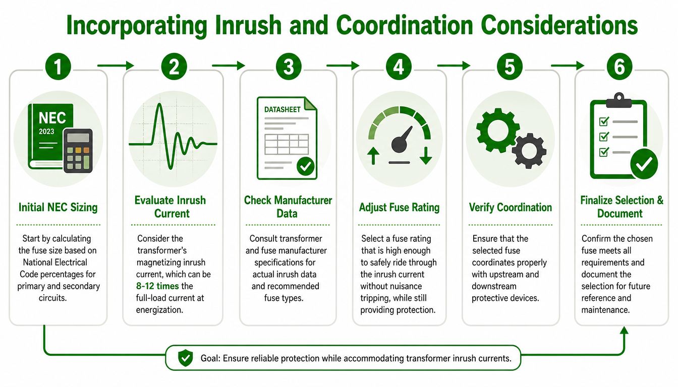
Incorporating Inrush and Coordination Considerations
A transformer can pass the primary fuse calculation and still open the moment it is energized. The reason is magnetizing inrush, a short-duration current surge that the steady-state percentage method does not show. Inrush may reach approximately 8 to 12 times full-load current, according to the Eaton fuse sizing guide. A fuse selected from arithmetic alone can therefore nuisance-open during startup while remaining suitable for continuous load current.
Start with manufacturer data
Get the transformer's inrush information, recommended fuse types, and time-current curves before increasing the fuse rating. Compare the inrush magnitude and duration with the fuse's minimum-melting and total-clearing characteristics. A properly selected fuse can ride through a brief high-current pulse while still opening for a sustained overload or fault.
Use this review sequence:
- Calculate the NEC-based starting point. Establish primary and secondary limits from verified transformer data.
- Locate inrush information. Check the transformer data sheet, manufacturer application notes, and specified fuse class.
- Compare time-current curves. Confirm that the fuse rides through energization while remaining within the required protection limits.
- Review the distribution lineup. Compare transformer protection with upstream feeder devices, the secondary main, and branch protection.
- Test the actual installation. Check voltage, switching order, load behavior, and control equipment that energizes with the transformer.
- Document the decision. Record the fuse rating, fuse type, source data, and reason for any adjustment.
If inrush data is unavailable, field technicians sometimes select the next larger standard fuse size to reduce nuisance openings. That can resolve a startup problem, but it also creates a protection risk. Without manufacturer data or curve analysis, increasing the fuse may hide the symptom while allowing a transformer or conductor fault to receive less immediate protection.
Balance continuity with fault containment
Commercial buildings require both reliable operation and controlled fault clearing. A primary fuse that opens during every energization can interrupt an entire tenant area. A fuse rated too high can permit transformer or conductor damage before the protective device operates.
EV charging equipment, VFD-controlled air-handling systems, and LED lighting networks may share one transformer while producing different startup and harmonic behavior. Confirm coordination through time-current curves rather than ampere ratings alone. If the proposed fuse exceeds the calculated starting point, identify the reason, verify the curve, and record the decision in the equipment documentation.
Practical Examples and Sizing Tables
The following examples use single-phase calculations so the arithmetic is visible. They illustrate the primary-only 125% method for transformers under 1,000 V, using the standard ratings listed in the NEC-based reference. They are calculation examples, not universal installation prescriptions.
| Transformer kVA | Primary Voltage | Full Load Current | Fuse Percentage | Selected Fuse Size |
|---|---|---|---|---|
| 15 kVA | 480 V | 31.25 A | 125% | 40 A |
| 50 kVA | 480 V | 104.17 A | 125% | 150 A |
| 150 kVA | 208 V | 721.15 A | 125% | Higher standard rating required, verify equipment and code limits |
The 15 kVA, 480 V example calculates as follows:
15,000 ÷ 480 = 31.25 A
Applying the primary-only limit gives:
31.25 × 1.25 = 39.06 A
The next listed standard rating is 40 A. This is a clean example because the calculated maximum falls close to a standard fuse size and doesn't require a large upward jump.
For the 50 kVA, 480 V transformer:
50,000 ÷ 480 = 104.17 A
Applying 125% produces 130.21 A, which moves to the next standard rating, 150 A. Before installation, verify whether the transformer has separately protected secondary conductors, because that changes the applicable primary ceiling and the coordination arrangement.
The 150 kVA, 208 V example produces:
150,000 ÷ 208 = 721.15 A
At 125%, the result is 901.44 A. The listed series moves beyond 500 A, so the technician must consult the complete applicable standard series, equipment ratings, conductor protection, and manufacturer instructions rather than guessing a fuse size.
How to use the table in the field
Write the formula beside the nameplate data. Then record whether protection is primary-only or primary-and-secondary, because the same transformer can produce a different permissible primary limit under the two arrangements. Finally, confirm that the selected fuse is compatible with the holder, disconnect, conductor ampacity, available fault current, and coordination study.
A table is useful for checking arithmetic. It isn't a substitute for reviewing the actual transformer and distribution system.
Tips and Common Pitfalls
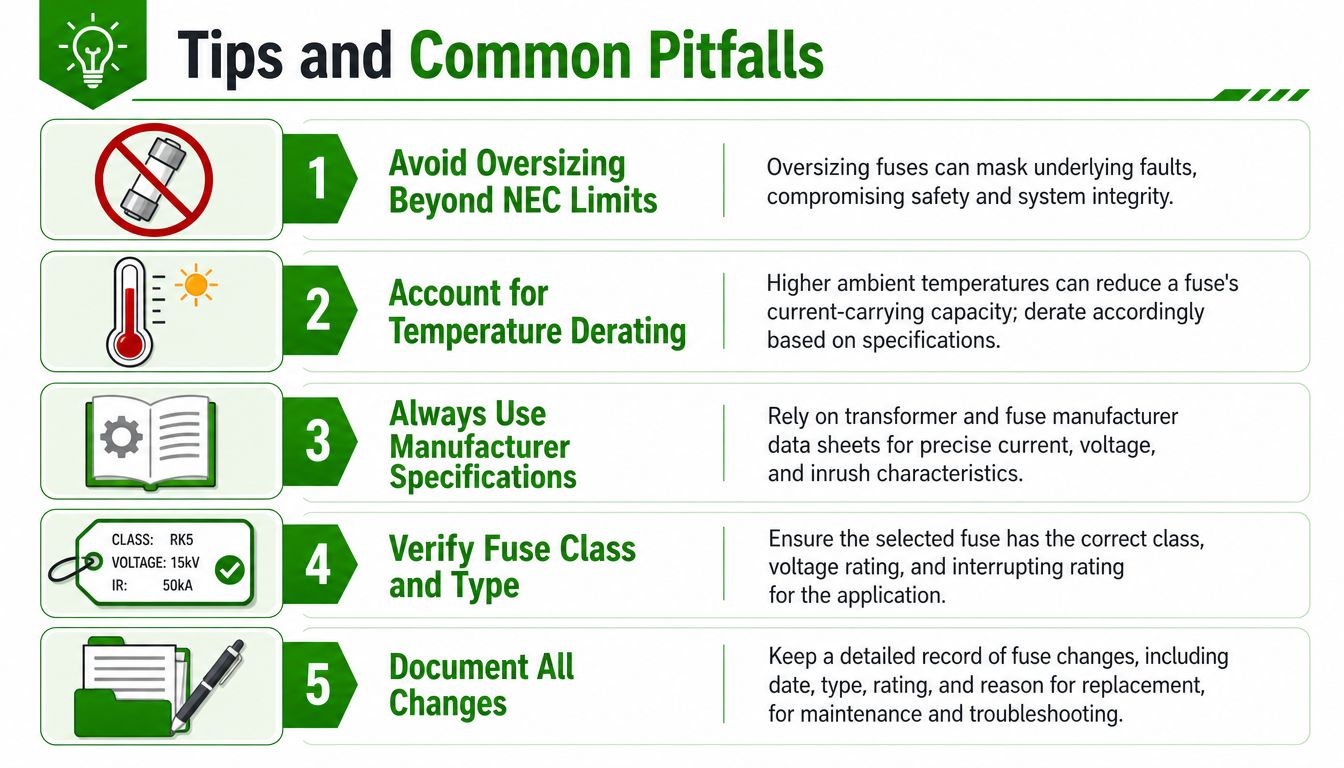
Fuse selection fails most often when technicians treat a percentage as the whole design. The number can be mathematically correct and still ignore inrush, temperature, fuse class, downstream coordination, or an altered load profile.
- Avoid oversizing beyond NEC limits: A larger fuse can mask an underlying overload or fault and may compromise transformer and conductor protection.
- Check ambient conditions: Higher temperatures can reduce a fuse's current-carrying capacity. Apply the manufacturer's derating information rather than assuming the panel environment matches the catalog condition.
- Use manufacturer specifications: Transformer inrush, fuse type, interrupting rating, and time-current data should guide any selection that differs from the basic calculation.
- Verify fuse class and type: Confirm voltage rating, class, interrupting rating, physical fit, and time-delay characteristics before installation.
- Document every change: Record the date, fuse rating, fuse type, reason for replacement, measured conditions, and any coordination review.
A fuse that opens repeatedly isn't automatically undersized. Investigate loose terminations, overheating, overloaded transformers, incorrect voltage taps, defective loads, and downstream faults before increasing the rating. Retest after maintenance and update the panel schedule so the next technician can see what changed and why.
Use this final check: verify the nameplate, calculate both sides, apply the correct NEC limit, check inrush, compare time-current curves, confirm coordination, inspect the installation, and document the result.
Access Electrical and Lighting provides commercial transformer protection support, including electrical troubleshooting, distribution upgrades, testing, and documented infrared inspections. Visit Access Electrical and Lighting to arrange a site review for fuse selection, nuisance-trip investigation, or broader commercial electrical maintenance.