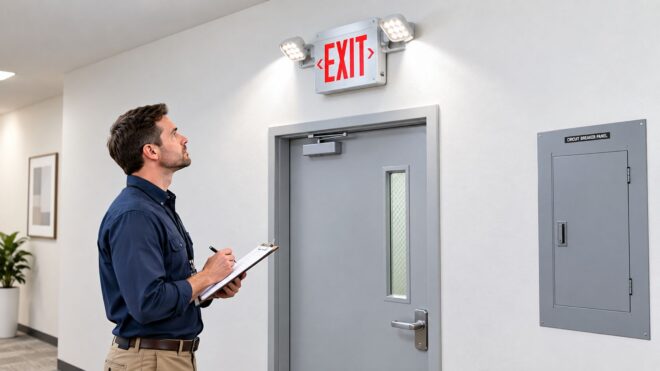
A fire inspector arrives for a routine walkthrough, and the facility manager is searching SharePoint for last quarter's emergency-lighting records. The exit signs look fine from the floor, but two fixtures at a rear exit won't hold their charge. The equipment problem is obvious. The missing test trail is just as serious.
That's the reality behind an exit sign emergency light combo. It isn't just a convenient fixture mounted above a doorway. It carries two life-safety duties in one housing, and both duties have to work when normal power fails. The illuminated exit legend must remain readable, while the integrated emergency heads must provide light along the egress route. The purchase matters, but the installation record, test history, battery condition, and corrective-action log determine whether the system remains useful and inspection-ready.
What an Exit Sign Emergency Light Combo Actually Does
An exit sign emergency light combo places a continuously illuminated EXIT legend and one or more adjustable emergency lamp heads in the same housing. Under normal conditions, building power keeps the sign lit and charges the internal battery. If normal power fails, a transfer circuit shifts the emergency lighting load to battery operation.
This arrangement fits doorways and egress points where the sign and emergency illumination serve the same area. One housing can reduce the number of fixtures above an opening, but it also creates one integrated device to identify, test, repair, and document. Units such as emergency exit lights with battery backup still require unit-level accountability, even when several fixtures serve one corridor.
Two functions, one inspection responsibility
The sign must remain legible during normal operation and during a power failure, with its location supporting visibility along the egress path. The emergency heads must illuminate the floor area occupants use to leave. NFPA-based guidance commonly requires emergency egress illumination for at least 90 minutes, with a benchmark of 1 foot-candle at floor level along the path of egress.
Those functions depend on more than a bright faceplate. The internal battery, charger, transfer circuit, LED boards, lamp-head wiring, and sign electronics all affect performance. A sign that looks normal on building power does not show whether the battery can operate the emergency heads. A charged battery also cannot correct a faded legend, failed LED board, loose connector, or heads aimed away from the route.
Field rule: Treat every combo unit as two life-safety functions with one service record.
Why combo units fail inspection
The recurring failures are straightforward:
- Weak or failed batteries: The fixture may appear normal until the test button is pressed or an extended discharge test is completed.
- Faded or incomplete legends: A damaged LED board, loose connector, or aging sign face can reduce readability.
- Misaligned lamp heads: The heads may turn on while leaving the required walking surface poorly illuminated.
- Missing documentation: A functioning fixture can still create an inspection problem when monthly and annual records cannot be produced.
The purchase is only the first control point. A combo unit remains a lifecycle compliance asset when the facility has a repeatable process for installation records, monthly testing, annual endurance testing, battery replacement, corrective action, and record retention. The battery is a service component, not a permanent part of the building. Track its condition and replacement cadence alongside the test paperwork, so an apparently operational unit does not become an undocumented failure during an inspection.
Code and Standards Requirements You Need to Know First
Start with the applicable code edition and the local Authority Having Jurisdiction, or AHJ, before comparing housings or battery chemistries. NFPA 101, the National Electrical Code, OSHA means-of-egress rules, and the product listing each address a different part of the installation. A unit that looks acceptable in a catalog may still be wrong for the occupancy, circuit arrangement, mounting condition, or local approval requirement.
The practical baseline is clear. NFPA-based guidance commonly calls for emergency illumination lasting at least 90 minutes, and it uses 1 foot-candle at floor level along the egress path as a minimum illumination benchmark. Exit signs also need continuous illumination, and many standards use a maximum viewing-distance concept of 100 feet or the sign's listed viewing distance, whichever is less. See the historical and code overview of exit-sign development for the relationship between egress safety and modern exit-sign requirements.
How the rule stack affects a purchase
NFPA 101 addresses life-safety conditions, including illuminated exits, egress visibility, emergency lighting duration, and placement. NEC Articles 700 and 701 influence how emergency circuits are supplied, separated, identified, and maintained. OSHA 29 CFR 1910.37 addresses workplace means of egress, including the need for exits and routes to remain recognizable and usable.
UL 924 is the product-side baseline for emergency lighting and exit-sign equipment. Look for an actual listing covering the complete combo assembly, not a general statement that a component is suitable for emergency use. The listing should match the installed configuration, including the sign face, lamp heads, voltage, battery arrangement, and mounting method.
Code and Standard Thresholds for Combo Units
| Requirement | NFPA 101 | NEC Article 700/701 | OSHA 1910.37 | UL 924 |
|---|---|---|---|---|
| Exit identification | Illuminated and legible exits | Emergency supply and wiring must be suitable for the circuit | Exit routes must remain recognizable | Sign assembly evaluated for emergency use |
| Emergency lighting | Commonly at least 90 minutes and 1 foot-candle at the egress path | Emergency circuit installation and continuity | Egress routes must remain usable during emergencies | Battery, transfer, and illumination performance evaluated |
| Sign placement | Visibility along the egress path, commonly using 100 feet or listed distance, whichever is less | Circuit and installation provisions apply | Route visibility and marking | Listed configuration and performance |
| Product construction | Must suit the occupancy and conditions | Wiring method and supply compatibility | Workplace safety application | Listing must cover the installed product |
Mounting details, legend color, letter dimensions, height, and charging-indicator requirements can vary by jurisdiction and occupancy. High-rise, healthcare, assembly, garage, and exterior applications often receive closer review than a small dry office. Confirm local amendments and approval requirements before ordering, because the AHJ has the final say on what passes in that building.
Choosing the Right Combo Unit for Your Facility
A combo unit can pass installation and still become a maintenance problem later. Select it as a lifecycle compliance asset. Compare the fixture's maintenance model, environmental rating, testing method, battery access, replacement parts, and recordkeeping support, not only the face color and lamp-head shape.
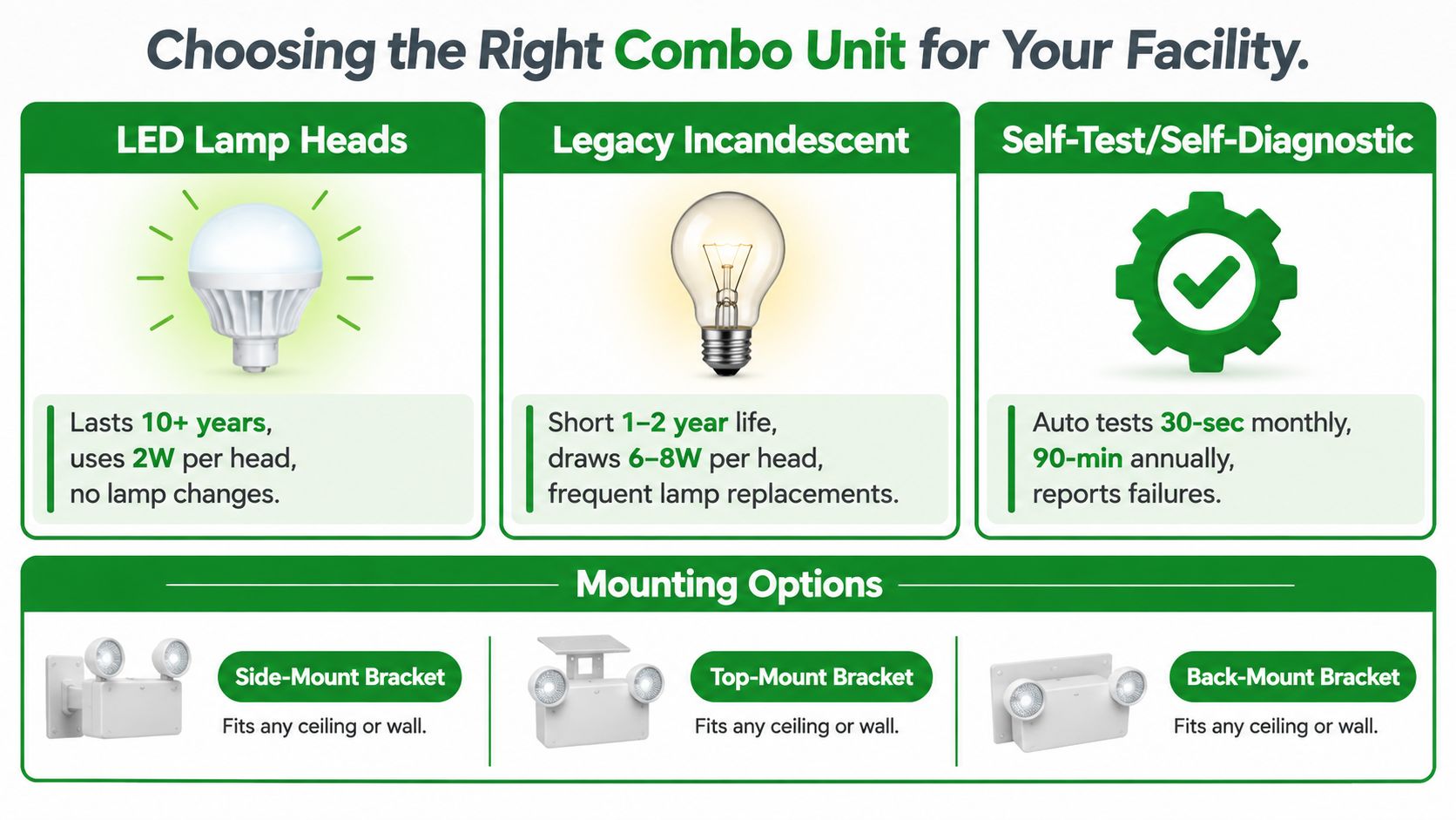
LED lamp heads are the practical choice for new commercial installations because they avoid routine lamp changes and work well with low-wattage emergency electronics. Illuminated exit signs in commercial and industrial settings are predominantly LED-based and draw less than 5 watts, or about 44 kWh per year per unit under continuous operation. Older incandescent units are commonly cited at about 40 watts. The energy comparison appears in this NFPA and exit-sign energy overview.
Compare the maintenance choices
| Decision | Usually works well | Watch for |
|---|---|---|
| Lamp technology | LED sign and LED heads for lower maintenance | Replacement boards and drivers must remain compatible |
| Testing method | Self-test equipment with exportable records | A flashing status light without a usable log may not satisfy documentation needs |
| Mounting | Universal side, top, or back mounting where the listing permits it | Field modifications can void the listed configuration |
| Legend | Red or green as accepted by the local requirement | Don't assume the preferred color is allowed everywhere |
| Battery | Chemistry selected for the environment and service plan | Cold, heat, charging conditions, and replacement availability matter |
| Housing | Damp or wet-location construction for exposed areas | A dry-location thermoplastic housing won't solve water intrusion |
Self-testing and self-diagnostic units reduce routine labor only when results remain visible and retrievable. An automated check with no usable history still leaves the facility manager with a paperwork gap. For a portfolio, select equipment that associates each result with the unit ID and location, then retain those records with the inspection file.
Battery access and replacement cadence deserve the same attention as the initial purchase. Confirm how the battery is reached, which replacement is listed, and whether the service team can identify the install date and test history without removing the entire housing.
Universal-mount housings simplify procurement and service across varied door conditions. Dedicated configurations can be cleaner when the mounting surface, face direction, or local approval is specific. Remote-head capacity helps in large open areas, but verify the listed output capacity and actual load before connecting additional heads.
Wet-location models belong in parking structures, exterior canopies, washdown areas, and spaces exposed to condensation or water. Contractor-grade fixtures suit ordinary conditions, while spec-grade products generally provide sturdier housings, clearer documentation, and better replacement support. Choose according to the property's inspection exposure and maintenance expectations.
Installing a Combo Unit the Way Inspectors Want to See
Installation starts with the egress path, not the box. Stand where an occupant approaches the exit and confirm the sign face is visible, the directional indication matches the actual route, and the emergency lamp heads throw light down the path rather than into a wall or ceiling obstruction.
The mounting arrangement must follow the product listing and the approved hardware. A wall-mounted unit, ceiling-mounted unit, and end-cap unit can use different canopy plates, gaskets, and fasteners. Improvised plates or unsealed conduit entries create avoidable problems, particularly in garages, canopies, and damp locations.
Placement and aiming
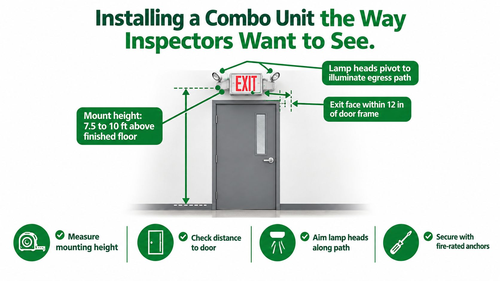
Use the manufacturer's spacing and photometric information when the area is large or irregular. For the doorway itself, the field target is a mounting height in the 7.5 to 10 foot range above finished floor, with the exit face within 12 inches of the door frame it serves, as specified in the installation plan for this guide. Those dimensions must still be reconciled with the listing, architectural conditions, accessibility requirements, and local AHJ direction.
Aim adjustable heads so the beam supports movement along the egress route. A head pointed at a nearby wall may look bright during a walkthrough but leave the floor poorly illuminated where people need to step. Check shadows around door swings, stair landings, shelving, columns, and corridor intersections.
Power and labeling
The normal-power feed should be on a dedicated unswitched circuit so occupants can't turn off the charger or sign by operating a local switch. Identify the circuit in the panel directory, mark the line-voltage feed at the junction box, and verify the emergency transfer after energizing the unit.
Use the manufacturer's gasket plate and approved anchors for the environment and mounting surface. Put a permanent circuit ID on every fixture, then record the installation date, battery type or lot information, location, and unit identifier in the master log. The commercial exit sign installation service guidance follows the same principle: the physical installation and the future maintenance record should agree.
Testing and Documentation Schedules That Pass
A test without a record is difficult to defend. The maintenance log should let an inspector or a new technician identify the exact fixture, locate it, review the result, and confirm what happened after a failure. Treat the log as part of the combo unit's lifecycle, not as paperwork added after installation.
Battery-powered combo units are typically checked with a monthly functional test lasting at least 30 seconds, followed by an annual full-duration test lasting 90 minutes. The monthly test confirms automatic transfer to battery mode. The annual test confirms that the battery can sustain the required emergency load for the full duration. These practices are described in NFPA Journal guidance on emergency-lighting testing.
What the technician should verify
During the monthly test, press the test button and confirm that the exit face remains legible and the emergency heads illuminate without flicker or obvious dimming. Record the date, unit ID, location, pass or fail result, and corrective action. Reset the fixture and confirm that the charging indicator returns to its normal state.
The annual discharge requires closer observation. Record the starting condition, check performance throughout the test, and verify operation through the full 90-minute period. The field benchmark is approximately 1 foot-candle average initially at the egress path, with illumination still meeting the lower allowable level at the end of the test. Use the applicable listing, adopted code, and AHJ direction when evaluating the installation. The battery-backed combo testing guidance also supports documenting the battery-backed test as a distinct maintenance event.
Documentation standard: Record the fixture, not just the building. “Emergency lights tested” isn't a useful maintenance entry.
Combo Unit Testing and Documentation Schedule
| Test Type | Cadence | Duration | Required Log Entry |
|---|---|---|---|
| Functional transfer test | Monthly | At least 30 seconds | Date, unit ID, location, sign status, lamp-head status, pass or fail |
| Full battery discharge | Annual | 90 minutes | Start condition, observations, end condition, illumination findings, corrective action |
| Repair verification | After a failure or repair | Until normal operation is confirmed | Failure cause, parts replaced, technician, retest result |
| Battery replacement review | Based on test results and service condition | Not a timed test | Battery date, replacement reason, new battery information |
Keep the log digitally or in a physical binder, but make it accessible. Include the fixture schedule, circuit IDs, installation dates, battery replacements, annual results, permits or certificates where applicable, and open corrective actions. Schedule battery replacement from test results and service condition rather than treating the purchase date as proof of remaining capacity. The emergency-lighting testing service information reflects the operational reality that testing, corrective work, and documentation belong in one maintenance program.
Troubleshooting Common Combo Unit Failures
A combo unit doesn't become reliable just because it passed commissioning. Batteries age, charging circuits drift, connectors corrode, and LED drivers fail independently of the battery. Visual inspection catches some problems, but a discharge test exposes failures that normal-power operation can hide.
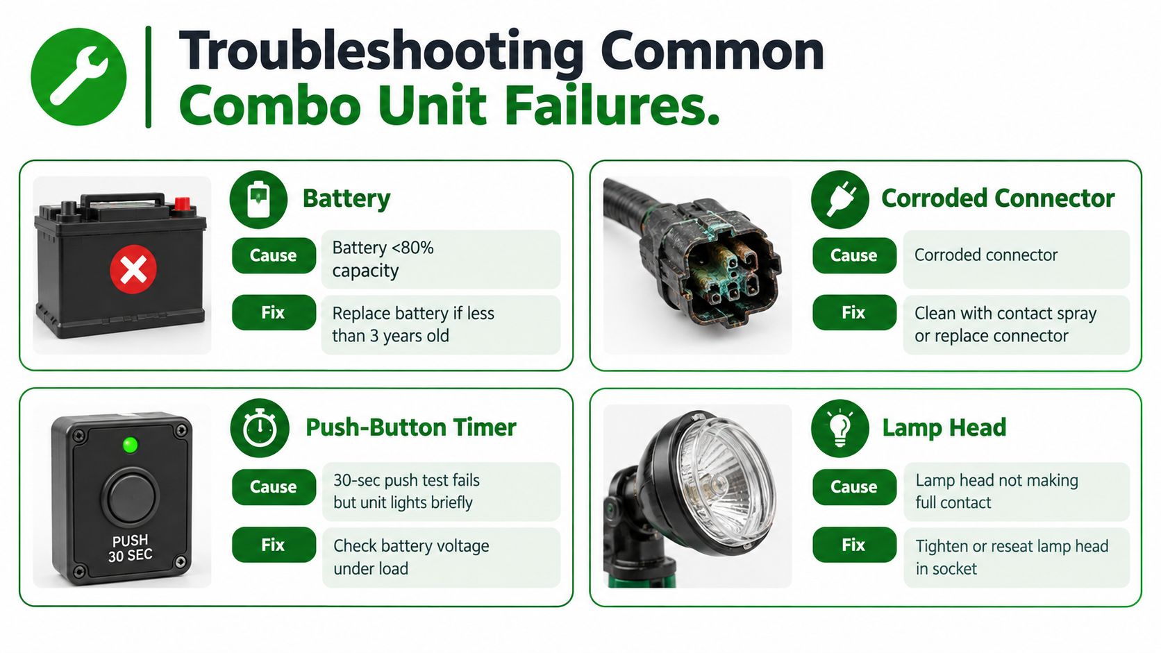
A fixture that lights briefly during a push test but fails to sustain operation points toward a battery or connection problem. Check the battery under load and inspect the harness for corrosion or a loose connector. Don't replace a sign face when the battery is the part failing.
Diagnose the symptom before replacing parts
A unit that passes a short functional test but dies before the annual duration may have an aged battery pack or a charger that isn't maintaining the correct float condition. A battery replacement may solve the problem, but verify charging performance before closing the work order. Otherwise, the new battery can fail for the same reason.
Flickering or partial EXIT letters usually points toward the LED board, driver, or an internal connector. If one lamp head illuminates and the other doesn't, inspect the individual LED module, pivot, socket, and wiring rather than assuming the shared battery is defective.
Use a consistent work-order record:
- Identify the symptom: Note whether the failure involves transfer, duration, sign legibility, flicker, or one lamp head.
- Test under the right condition: Check battery voltage and charging behavior under load when the symptom concerns runtime.
- Inspect connections: Look for corrosion, loose plugs, damaged pivots, and heat-related discoloration.
- Confirm the repair: Repeat the relevant functional or duration test and record the result.
A recurring failure pattern is often a maintenance-planning problem rather than a product mystery. If several units from the same installation period fail endurance testing, group the battery replacements and review the charger condition, environmental exposure, and documentation history.
A Simple Lifecycle Plan for Combo Units
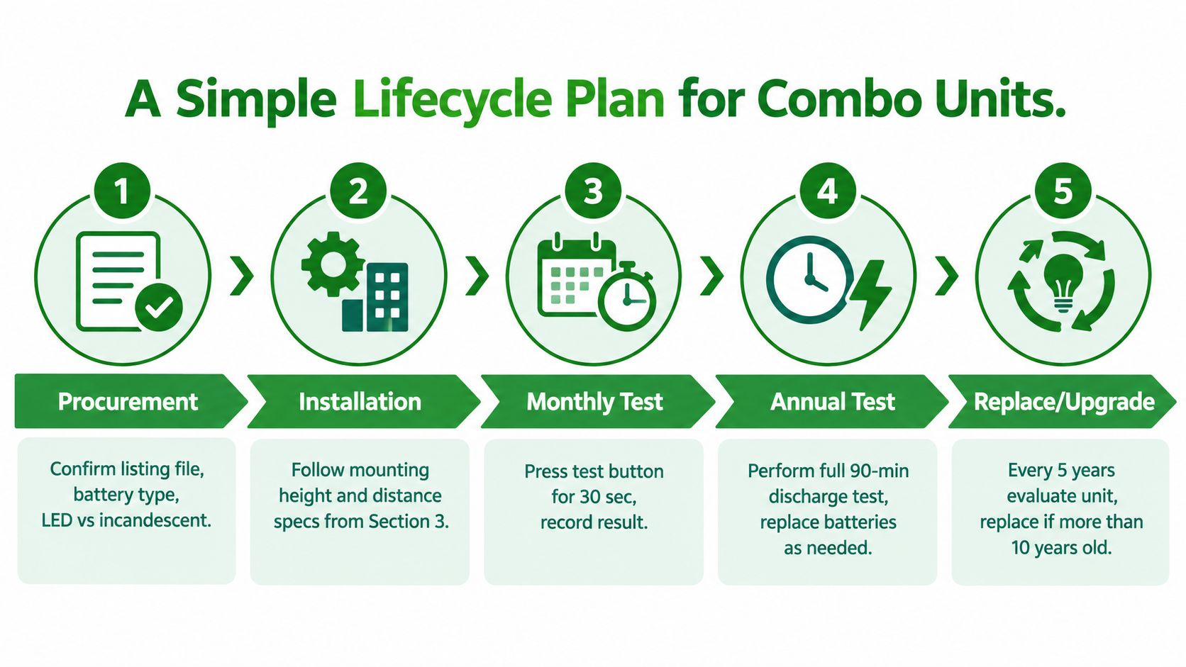
The cleanest handoff is a lifecycle checklist that starts before the fixture arrives. Procurement should confirm the product listing, face configuration, battery type, voltage, mounting option, environmental rating, and remote-head requirements. Keep the purchase record with the facility's emergency-lighting documentation so the replacement part and original configuration can be traced.
Installation records should include the circuit ID, mounting location, initial aiming check, charging indicator, transfer test, and commissioning result. From there, the maintenance calendar needs a standing monthly functional test and an annual full-duration test, with failures assigned to a named technician or vendor instead of left as an informal note.
The handoff checklist
- Procurement: Confirm the listed assembly and the exact mounting and battery configuration.
- Installation: Label the circuit and fixture, verify the egress coverage, and record the commissioning test.
- Monthly service: Perform the short transfer test and log the result by unit.
- Annual service: Perform the full discharge test and document any illumination or runtime deficiency.
- Replacement planning: Review batteries when test performance declines and evaluate the complete fixture during remodels, code updates, or repeated failures.
Battery replacement shouldn't be driven by a calendar alone. Test results, charging behavior, temperature, and manufacturer instructions determine whether a battery remains serviceable. For properties using self-testing or centrally monitored equipment, preserve the exported records and confirm that the system identifies the affected fixture rather than reporting only a broad zone.
The final file should contain the invoice, listing information, installation records, permits where applicable, monthly logs, annual test certifications, repair work orders, and battery replacement receipts. Store it where the inspector and the next maintenance hire can find it without a scavenger hunt.
Access Electrical and Lighting installs, tests, maintains, and repairs commercial exit signs, emergency lighting, and battery-backup systems for offices, retail properties, and multifamily buildings. Visit Access Electrical and Lighting to request a fixture assessment, documented testing program, or repair plan for your property.