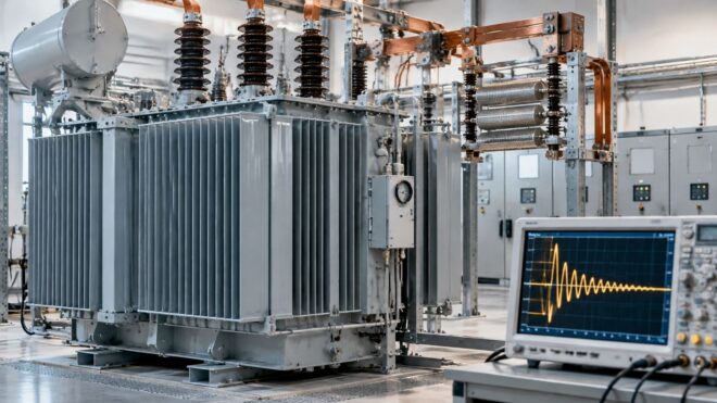
Power returns after an evening outage, your building engineer resets the main, and the transformer breaker trips again within seconds. There's no smell of heat, no failed load, and a test later shows the transformer is healthy. That sequence confuses many facility teams because the equipment that tripped did exactly what its settings told it to do, just for the wrong reason.
The culprit is often inrush current in transformer energization. It's a brief magnetizing surge that happens when the core builds magnetic flux at switch-on, and it can look, for a few cycles, like a fault. Understanding it matters because the wrong response, upsizing a breaker until the trips stop, can leave conductors and the transformer itself underprotected.
The practical approach is different. You learn what range of surge is credible for your specific unit, you capture what happens at energization, and you match protection to that evidence before you buy limiting hardware.
Inrush Multiples at a Glance
A transformer's steady no-load current can be small, while its brief energization surge is much larger. A single-phase power-transformer investigation published in the Scientific Bulletin places no-load current near 1–2% of rated current and reports energization inrush of approximately 10–20 times rated current. The contrast explains why a healthy transformer can still challenge protection at switch-on.
In that investigation, calculated inrush amplitudes were 1,371 amperes and 1,199 amperes for a transformer with rated current of approximately 15 amperes and steady-state magnetizing current of 0.22 amperes. Those results are specific to the transformer and test conditions. A single multiplier cannot predict the peak for every transformer and switching instant.
| Source of the figure | Multiple of rated current | Practical meaning |
|---|---|---|
| Normal no-load magnetizing current | 1–2% of rated current | Steady state, barely noticeable |
| Commonly cited energization inrush | 10–20 times rated current | Range reported in an academic study |
| IEEE practical range at nominal voltage | 10–12 times full-load current | Planning reference from the IEEE Power System Relaying Committee report |
| Manufacturer envelope for several cycles | 5–25 times primary full-load amps | Use the OEM figure, not a generic multiplier |
| Laboratory 1 kVA, 220/110 V unit | Up to 10 times rated current | Small-transformer test result |
| Documented field example | 3.4 times pre-outage current (580 A) | Plateau of about 0.3 seconds |
How to Read Each Row
Use the IEEE planning range for early coordination studies when manufacturer test data is not yet available. For an actual breaker, fuse, or relay setting, start with the manufacturer's envelope for the specific transformer. The laboratory result gives another reference point: a 2024 study of a 1 kVA, 220/110 V, 50 Hz single-phase transformer reports inrush of up to 10 times rated current.
The field example shows that a recorded peak can fall below the planning range. Unfavorable switching can push the peak well above it. Neither figure predicts the next energization, because the result depends on the switching instant and the core's residual flux.
Practical rule: For a specific installation, use the manufacturer's inrush envelope as your starting point, then compare it with a captured waveform and the protective device's response.
Read the table as a set of reference points, not a universal setting. The right protection choice depends on the credible inrush for that transformer and the breaker or relay protecting it.
How Inrush Forms and What Sets Its Peak
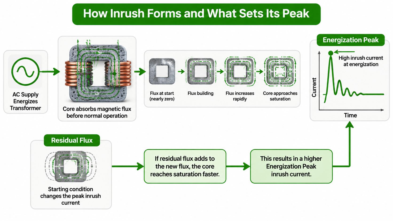
At switch-on, a healthy transformer can draw a surge before it settles into normal operation. The core must build magnetic flux, much like a sponge taking up water. If magnetism left from the previous shutdown is already pushing in the same direction, the new flux can exceed the core's normal operating range.
That condition is core saturation. An IEEE Power System Relaying Committee report on transformer inrush explains that residual flux and the switching instant can push flux beyond its normal range. Saturation sharply reduces the core's effective magnetizing impedance, allowing a large, asymmetric current to flow. For preliminary planning at nominal voltage, the report gives a practical range of 8–12 times rated current. That range is a starting point, not a prediction for every transformer: the actual peak depends on the unit, its supply, and the instant each breaker pole closes.
The Sequence From Closing to Decay
- The breaker closes at a particular voltage angle. That instant sets how flux begins to build during the first half-cycle.
- The applied voltage builds flux over time. Flux accumulates in one direction until the voltage reverses.
- Residual flux adds to or subtracts from the new flux. Magnetism left after shutdown can soften the first peak or drive it higher.
- The core saturates and current spikes. As magnetizing impedance falls, current surges in a strongly one-sided waveform.
- The surge decays toward normal. As flux returns toward its regular trajectory, current approaches the smaller steady-state magnetizing current.
The connected load has little bearing on this initial surge. Inrush is a magnetizing transient, so switching off downstream loads does not remove the core's need to build flux. That is why load shedding alone may not resolve trips during restoration.
What the Waveform and Timing Tell You
A recorded inrush waveform typically rises sharply on one side, departs from a clean sine wave, and remains asymmetric for several cycles. That shape helps distinguish a magnetizing transient from normal load current when reviewing a relay or oscilloscope record.
Decay time depends on the source and transformer impedances and tends to be longer for larger units. A generic multiplier cannot capture every credible peak: energization angle and residual flux magnitude and polarity usually have the greatest influence, followed by transformer impedance, source impedance, and core characteristics. Breaker closing scatter also matters because the poles may close at slightly different instants, producing different peaks across the phases.
Two otherwise identical transformers can therefore respond differently at different switch-ons. The hardware may be unchanged; the residual flux and closing instant are not. For a specific installation, compare the measured waveform with the transformer's characteristics and the breaker's actual response before changing settings or equipment.
Why Inrush Trips Breakers and Differential Relays
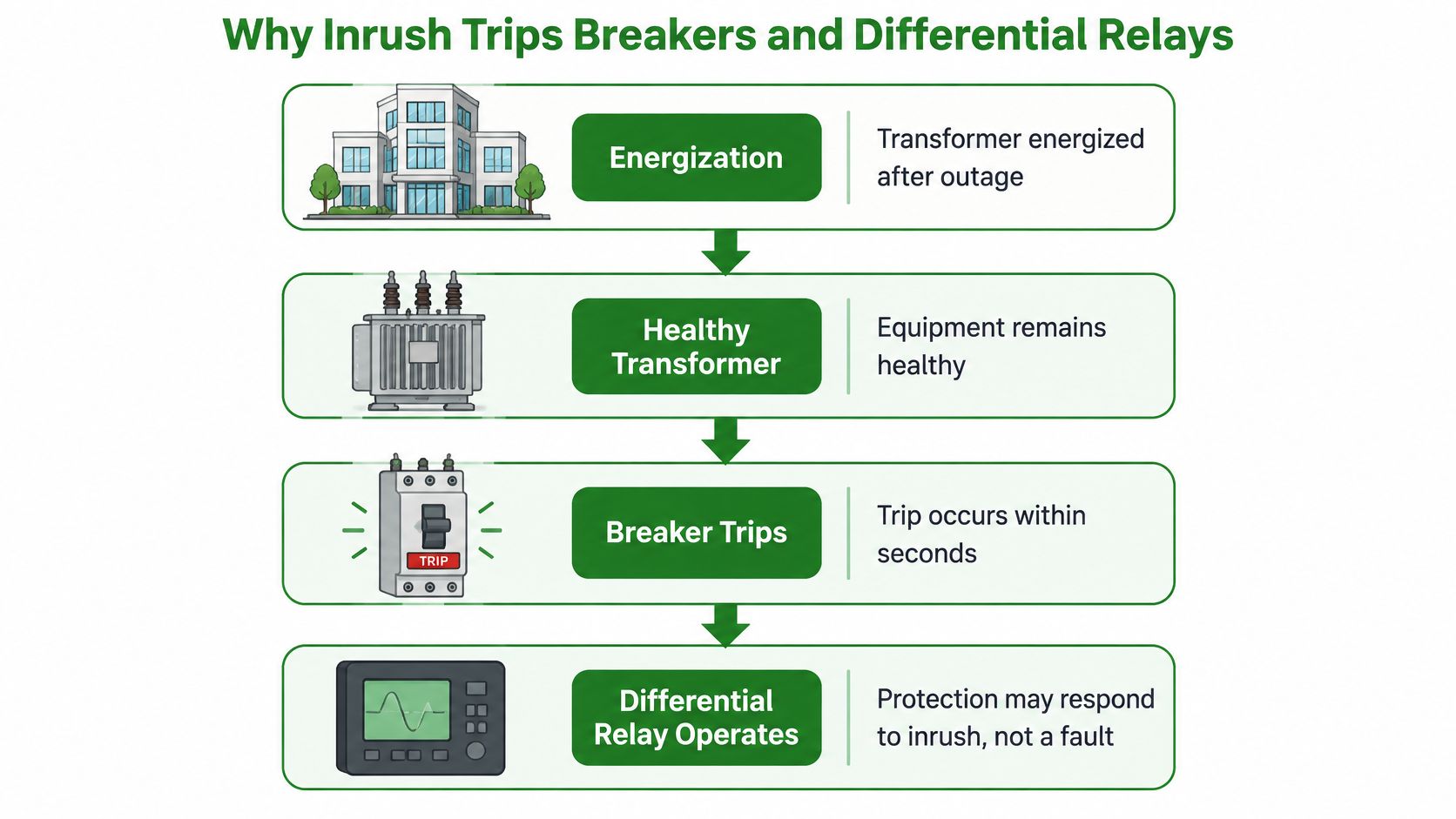
A trip at energization doesn't mean your transformer is faulty. That's the assumption to drop first. A perfectly healthy unit can draw a surge that crosses an instantaneous trip setting, and the breaker, which can't know why current is high, opens exactly as designed.
The wider risks explain why you shouldn't ignore those trips either. A heavy energization surge can cause voltage sag that flickers lighting or stalls motors, nuisance operation of overcurrent or differential protection, and mechanical stress on windings from the forces that large currents create. When several transformers and large LED driver loads energize together during restoration, the combined disturbance can also interfere with emergency power transfer or generator stability, which is one reason your electrical distribution systems layout and restoration sequence matters as much as any single device setting.
The Relay Problem in Plain Terms
Differential relays protect against internal winding faults by comparing current entering and leaving the transformer. During energization, magnetizing current flows in one side only, so the relay sees a difference that resembles an internal fault. What saves the scheme is waveform character. A Basler transformer protection application guide explains that the saturated core produces a nonsinusoidal magnetizing current, the second harmonic commonly becomes the predominant harmonic component, and differential relays use second-harmonic restraint or blocking to avoid interpreting energization current as an internal winding fault.
That restraint creates a genuine trade-off, often called security versus dependability. Too much restraint can delay or prevent tripping for a real internal fault, which puts the transformer at risk. Too little restraint produces an unwanted differential trip at energization, which puts your building in the dark.
Say a restored feeder energizes two transformers in sequence. The first relay's restraint is set correctly, it recognizes the harmonic signature, and it stays quiet. The second relay's restraint is set too low, its differential element trips, load shifts suddenly, and the disturbance cascades toward the generator transfer equipment. Nothing failed inside either transformer. One numerical setting made the difference.
What Modern Schemes Check Beyond Harmonics
- Waveform shape and current slope: Relays examine how the current rises and flattens, not just how big it gets.
- Flux estimation and zero-crossing behavior: These tests ask whether the pattern fits a saturating core rather than a short circuit.
- Phase-specific logic and time supervision: Each phase is judged on its own closing conditions, with timers that prevent a snap decision.
Don't overlook the current transformers feeding the relay. CT saturation and unequal CT performance can create differential current independently of inrush, so validate settings against the actual transformer ratio, vector group, CT characteristics, grounding arrangement, and expected energization sequence. A commissioning test should prove the relay stays restrained during normal energization and still trips promptly for simulated internal fault conditions.
Measuring Inrush With Oscilloscopes and Relay Records
Measurement turns an argument about multipliers into a verified number for your transformer. IEEE's TechNav overview of inrush current reports that manufacturer application data commonly specifies a broader possible range of 5-25 times primary full-load amps for several supply cycles, and it recommends using the manufacturer's measured or guaranteed inrush envelope rather than a generic multiplier. It also notes the transient flux is determined by the time integral of applied voltage and strongly affected by residual core flux, so an unfavorable closing angle can drive the core into saturation and produce a highly asymmetrical waveform.
| Method | What it captures | Best use |
|---|---|---|
| Manufacturer inrush envelope review | Published peak and decay range | Setting protection before installation |
| Field energization capture | Primary current against time during first energization | Commissioning new or replaced transformers |
| Oscilloscope or current-clamp recording | Waveform shape, peak, decay time and harmonic content | Investigating repeated trips |
| Digital relay event record | Initial current and voltage samples, peak inrush, voltage dip, second- and fifth-harmonic content | Post-trip diagnosis using stored data |
| Electromagnetic-transient model | Worst credible peak across varied closing angles | Large or uncertain systems |
| Infrared follow-up inspection | Hotspots at connections after repeated transients | Confirming no thermal damage after events |
Work through those methods in the order a facility normally would. Start on paper with the manufacturer envelope, because it's free and it frames every later capture. Move to field energization capture at commissioning, when you can record primary current under controlled conditions instead of during a chaotic outage restoration.
If trips repeat, an oscilloscope or recording current clamp gives you waveform shape, peak, and decay in enough detail to separate magnetizing inrush from a downstream fault. Before renting instruments, though, pull the digital relay event record already stored in your switchgear, since many relays have recorded the very event you're arguing about. Reserve an electromagnetic-transient model for large or uncertain systems where you need to test many closing angles you can't safely reproduce in the field.
A Commissioning Capture in Five Steps
- Confirm the OEM energization envelope before energizing, and note the peak and duration your protection must ride through.
- Record primary current through first energization with a recording clamp, oscilloscope current probe, or relay recorder armed in advance.
- Measure peak magnitude and decay time, including how many cycles pass before the waveform looks symmetrical again.
- Compare the capture against settings, specifically the instantaneous trip, short-time, and differential elements that could operate during those cycles.
- Repeat with a recorded closing angle if the first capture looks unrepresentative, because one gentle energization doesn't prove the worst case is safe.
On the oscilloscope itself, set the trigger on the rising edge of primary current so the sweep starts at closing, choose a sampling rate that resolves the first peak cleanly, and record long enough to cover several cycles of decay. Export the peak value and harmonic content rather than relying on a photograph of the screen, because your protection engineer needs numbers that can be plotted against time-current curves.
Interpreting the result is straightforward. If the captured peak crosses an instantaneous or differential threshold before restraint can act, your settings need to change, however healthy the transformer is. If the peak sits comfortably below every operating element with decay complete inside the expected window, your settings are acceptable and repeated trips point elsewhere, toward CT problems, wiring errors, or a genuine fault.
Mitigation Options From Coordination to Controlled Switching
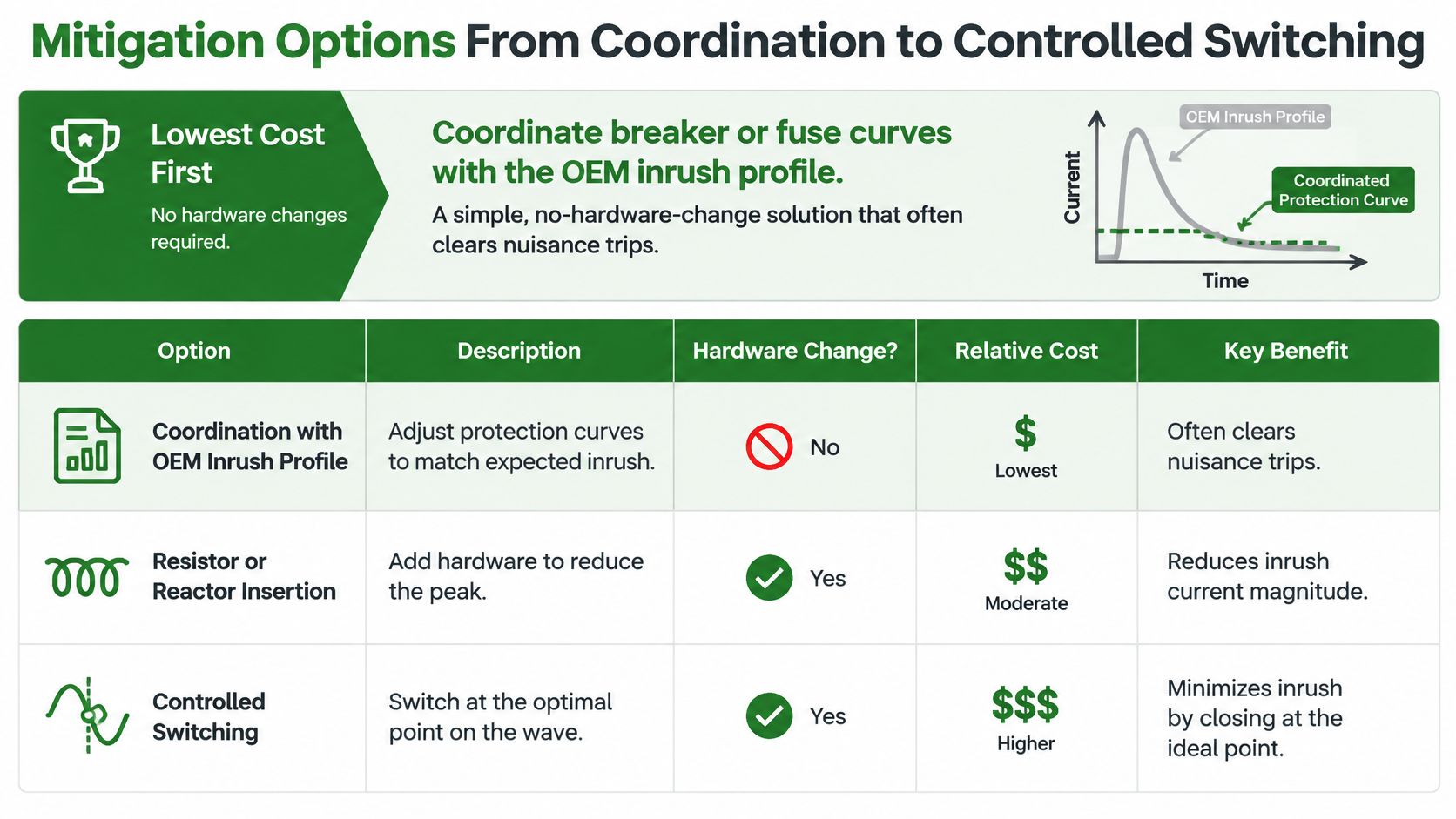
Begin with the cheapest fix, because it changes no hardware at all. Protection coordination means matching breaker or fuse time-current curves to the OEM inrush profile, so legitimate energization rides through while real faults still clear quickly. A careful review of fuse sizing for transformers against magnetizing inrush data clears many nuisance trips that teams were ready to solve with new equipment.
| Option | How it limits inrush | Best fit | Main limit |
|---|---|---|---|
| Protection coordination | Matches breaker or fuse curves to the OEM inrush profile | Most commercial sites | Does not reduce the transient itself |
| Pre-insertion resistor | Inserts resistance before the closing contacts bypass it | Repeated energization or generator transfer | Adds equipment and switching hardware |
| Series impedance | Adds impedance that damps the peak | Specific upstream constraints | Adds losses and voltage drop in service |
| Soft-start equipment | Ramps the voltage applied to the transformer | Sensitive loads and paralleled units | Adds power-electronic equipment to maintain |
| Controlled point-on-wave switching | Closes at a favorable voltage angle to limit flux offset | Breakers with known timing data | Fixed angle is not universally reliable |
| Inrush limiter | Limits peak through device-specific impedance | Retrofits where protection changes fail | Must be rated and coordinated for the specific unit |
Hardware options attack the surge itself rather than tolerating it. A pre-insertion resistor puts resistance in series for the first moments, then the closing contacts bypass it once flux has settled. Series impedance damps the peak continuously but charges you losses and voltage drop every hour in service, while soft-start equipment ramps applied voltage so flux builds gently instead of in one step.
Where Controlled Switching Earns Its Cost
Controlled point-on-wave switching closes each pole at a favorable voltage angle to reduce flux offset. The results can be substantial. A 2025 simulation study of optimized reclosing reported that an optimized reclosing strategy reduced peak inrush by more than 50% versus conventional closing in a modeled 132/33 kV, 63 MVA transformer.
Respect the limits behind that headline. Controlled switching must account for transformer connection, residual magnetism, pole-to-pole operating variation, and the switching device's actual timing, so a fixed closing angle isn't universally reliable. Reinforcement-learning methods that select energization timing remain research-stage rather than routine solutions for ordinary building transformers.
Don't automatically upsize a breaker to stop energization trips. A larger device that ignores inrush may also ignore the overloads and faults it exists to clear, compromising conductor and transformer protection.
Read the table by best fit, not by novelty. Coordination solves most commercial cases because the surge is tolerable once settings respect it, while engineered limiting earns its place when the surge itself causes harm, through voltage dips, relay misoperation, or generator instability that no setting change can remove.
Choose the Right Inrush Fix for Your Building
Size your answer against the worst credible inrush for your specific transformer and breaker, not against a memorized multiplier. A technical review in Electrical India on evaluating transformer switching transients reports published values ranging from roughly 10-15 times rated current, while emphasizing the actual envelope depends on switching angle, residual core flux, source impedance, core characteristics, breaker closing scatter, and transformer construction. That's exactly why a generic 8x, 10x, or 12x rule isn't a defensible sizing basis on its own.
Gather these inputs before anyone changes a setting:
- OEM inrush envelope: The manufacturer's peak and decay data for your exact unit, checked while you calculate transformer size and ratings for the installation.
- Protection time-current curves: Every breaker, fuse, and relay element that could operate in the first cycles.
- Available fault current and transformer impedance: Both shape the peak and the decay you'll see.
- Energization sequence after outages: Which transformers and loads close together during restoration.
Then follow the decision in order. If trips happen only on restoration, coordinate the curves first. If relays misoperate or voltage dips repeat, capture waveforms and pull relay records before buying hardware. If captures confirm repeated stress, evaluate a pre-insertion resistor, soft-start, or controlled switching, and verify any change with an infrared follow-up to confirm connections haven't suffered thermal damage.
Remember that shedding load won't remove magnetizing inrush, because the transient is a core-energization event. Access Electrical and Lighting, a licensed and bonded California C-10 contractor, license 952234, serving Orange County, provides electrical testing, infrared inspections with documented reports, and switchgear and panel upgrades, and a licensed commercial contractor can run the capture, review relay records, and perform that infrared inspection for your building.
If your transformer trips on restoration and you're weighing a settings change against new limiting hardware, get the energization captured and the relay records reviewed before anything is upsized. Access Electrical and Lighting provides electrical testing, infrared inspections with documented reports, and switchgear and panel upgrades for commercial properties across Orange County. Visit Access Electrical and Lighting to schedule an assessment of your transformer's inrush behavior.