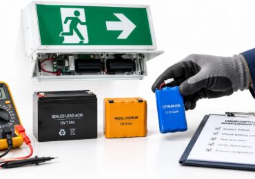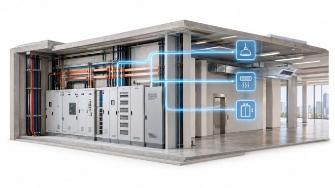
A switchgear failure rarely arrives at a convenient time. A property manager may get the call on a Saturday afternoon, just as tenants are using elevators, refrigeration, air conditioning, access control, and emergency systems. One failed connection or breaker can shut down a portion of the building, damage equipment, and turn a routine maintenance issue into an urgent operational problem.
That's why commercial electrical distribution systems deserve more attention than a one-line diagram reviewed only during a construction project. The system determines how power reaches every tenant and critical building function, how faults are contained, and whether new loads such as EV chargers or heat pumps can be added without creating nuisance trips and overheating.
What a Commercial Electrical Distribution System Actually Does
A commercial distribution system takes utility power at the service entrance and divides it into usable, protected circuits throughout the property. It supplies lighting, HVAC equipment, elevators, pumps, tenant improvements, receptacles, kitchen equipment, security systems, and life safety loads. The system must deliver that power at the correct voltage while isolating faults quickly enough to protect people, conductors, and equipment.
The practical difficulty is that the system works as a hierarchy. The utility service feeds the main switchgear. Main equipment feeds distribution sections, transformers, panels, motor control centers, and branch circuits. Each layer has to carry its intended load and coordinate with the protective devices above and below it.
A distribution system is not just a collection of breakers. It's a containment strategy for electrical faults.
Consider an office building with a loose feeder termination inside the main switchgear. At first, the connection may produce heat without interrupting service. Later, thermal cycling can worsen the connection, degrade insulation, and trigger a feeder trip. If the protective settings or equipment condition are poor, the fault may affect more than the original tenant circuit. The property team then has to manage dark work areas, failed HVAC equipment, elevator disruption, tenant complaints, and potentially unsafe electrical-room conditions.
The scale of distribution infrastructure explains why its condition matters beyond one property. The International Energy Agency's analysis of electricity grids reports that distribution grids account for approximately 93% of total global grid length. The same analysis says global grid length has expanded by roughly 1 million kilometers per year over the past five decades, while distribution networks grew by more than 40% during the decade covered and have nearly doubled over approximately the past 25 years.
For a property manager, the lesson is direct. Local distribution assets are where much of the customer-facing reliability risk sits. A building can have adequate regional generation and still lose service because of a failed panel, feeder, transformer, breaker, or connection on the property.
Why the layers matter operationally
A properly arranged system keeps a problem close to its source. A tenant receptacle fault should trip its branch overcurrent device, not the distribution panel main. A mechanical fault should affect the designated feeder while preserving unrelated tenant and life safety circuits. That selectivity depends on equipment condition, correct settings, accurate labeling, and a design that separates critical loads.
A facility team that understands this hierarchy can make better decisions. Instead of asking only whether a breaker is on or off, the team can ask which upstream device protects it, what other loads share the path, and how much of the building would be affected by a failure.
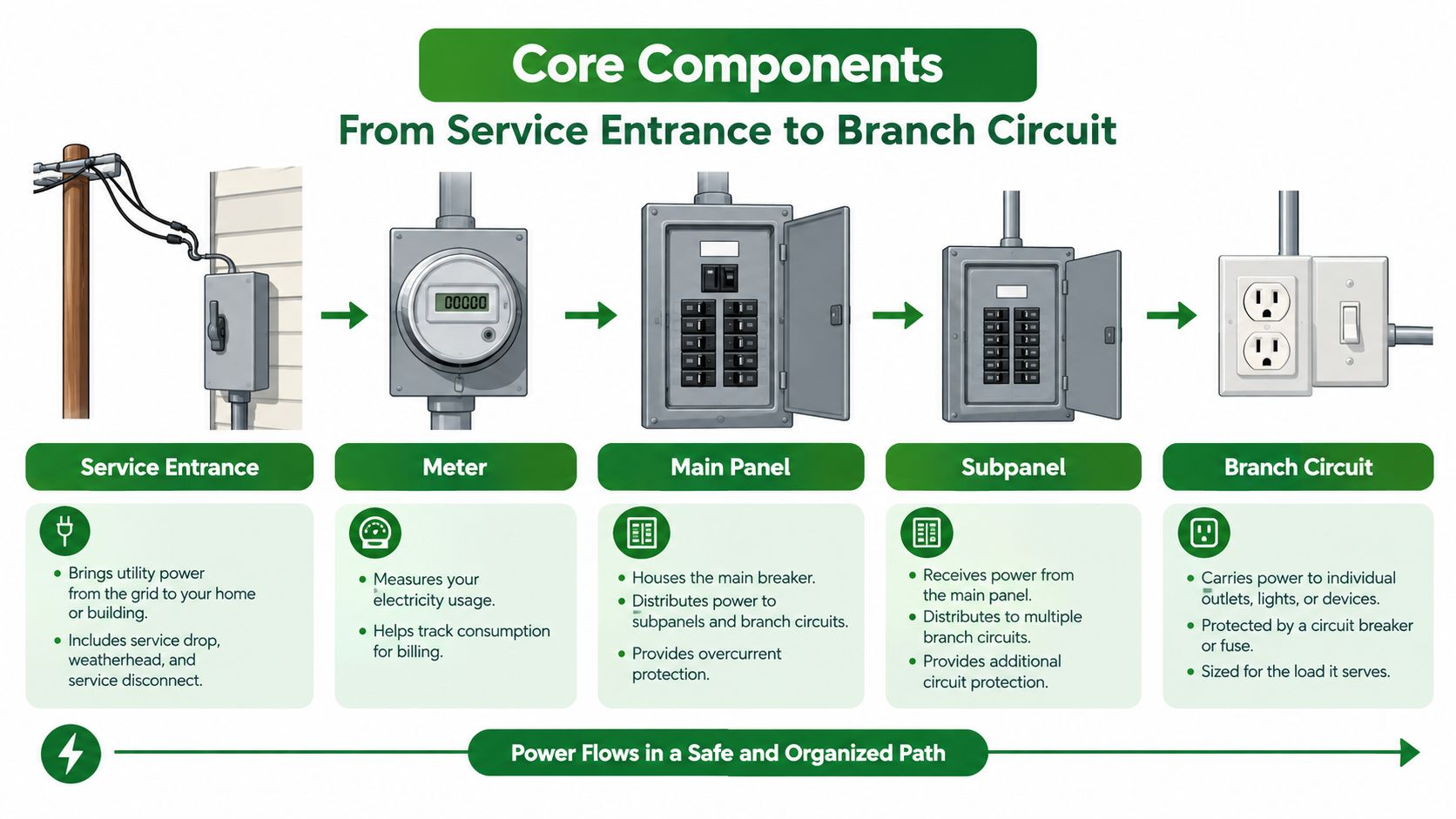
Core Components From Service Entrance to Branch Circuit
Think of the distribution system as a building's transportation network. The service entrance is the main gate, switchgear is the controlled receiving area, transformers are voltage-conversion stations, panels are local distribution hubs, and branch circuits are the final routes to equipment.
The power path
Service entrance and metering
Utility conductors enter through a service point, often connected to a utility vault, service section, or outdoor service equipment. Metering records consumption, while the service disconnect and main overcurrent protection provide the primary means of isolation and protection.Main switchboard or switchgear
This is the property's primary electrical hub. It contains busbars, main breakers, feeder breakers, protective relays where applicable, metering, and often surge protective devices. The bus distributes power across the lineup, while feeder breakers send protected power to downstream equipment.Transformers
Commercial buildings commonly use transformers to step utility or distribution voltage down to a voltage suitable for tenant and building loads. A transformer's enclosure, ventilation, connections, grounding, and loading all affect its reliability. Heat and poor terminations are recurring concerns, not minor housekeeping issues.Distribution panels and motor control centers
Panels divide feeders into smaller circuits. Motor control centers organize starters, disconnects, overload protection, and controls for mechanical equipment such as pumps and air-handling systems. These sections should be labeled clearly enough that a technician can identify the source and downstream function without guessing.Branch circuits and final loads
Branch circuits supply lighting, receptacles, rooftop units, pumps, kitchen equipment, elevators, tenant equipment, and controls. The final circuit is where occupants experience the result of a fault, but the cause may be farther upstream.
What the protective devices accomplish
Overcurrent devices interrupt excessive current caused by short circuits, overloads, or equipment faults. Disconnects provide a controlled isolation point for service work. Busbars carry current within switchboards and panels, and their joints must remain tight, clean, and properly supported.
Load segregation is equally important. Life safety systems, emergency equipment, mechanical loads, and tenant circuits often require different upstream arrangements. Separating them limits the blast radius of a fault and helps the facility team restore non-affected functions while troubleshooting the failed section.
Surge protective devices and power meters are usually installed where they can protect or monitor meaningful portions of the system. Their location matters. A device that monitors only one panel won't reveal a problem on a separate mechanical feeder, and a surge protective device installed without a sound grounding and bonding arrangement won't solve every power-quality issue.
Reading a Single-Line Diagram and Calculating Load
A single-line diagram compresses a three-phase electrical system into a readable map. It doesn't show every conductor separately. Instead, it shows how the service, disconnects, switchgear, transformers, panels, feeders, and loads connect.
Start at the utility service and trace one path downstream. Identify the main overcurrent device, each feeder breaker, every transformer, and each panel or disconnect. Then compare the diagram with the equipment in the electrical rooms. Missing labels, abandoned equipment, undocumented tenant work, and field changes can make an accurate drawing more valuable than a new piece of equipment.
A practical reading method
Look for these details:
- Source identification: Confirm the utility service, generator, automatic transfer equipment, or other source feeding each section.
- Protection points: Mark the main, feeder, and branch overcurrent devices. Note which device should operate first during a fault.
- Voltage changes: Follow each transformer and verify the primary and secondary voltage shown on the drawing.
- Load separation: Identify life safety, emergency, mechanical, tenant, and general building loads.
- Field verification: Compare circuit names, breaker sizes, conductor paths, and equipment tags with the installed system.
A load calculation starts with connected loads, but connected load isn't the same as expected demand. Lighting, receptacles, motors, HVAC equipment, elevators, kitchen loads, EV chargers, and future tenant equipment may not operate at the same time or at full output. NEC Article 220 provides the framework for applying applicable demand considerations, but the calculation still needs real operating information.
| Load Category | Demand Factor | Notes |
|---|---|---|
| Lighting | Apply the factor required by the applicable code method | Use connected lighting load, occupancy information, operating schedules, and any control strategy. |
| Receptacles | Apply the factor required by the applicable code method | Separate general receptacles from dedicated equipment and specialty tenant loads. |
| Motors | Apply the factor required by the applicable code method | Account for motor characteristics, starting conditions, and the applicable motor rules. |
| HVAC and mechanical equipment | Apply the factor required by the applicable code method | Review simultaneous operation, staging, electric heat, and seasonal operation. |
| EV charging and electrification | Model coincident demand and control strategy | Don't assume every charger or electric heating load operates independently of the building peak. |
For a deeper calculation workflow, review this guide to calculating transformer size. The result should support decisions about feeder capacity, transformer loading, voltage drop, protective settings, and available space, not merely produce a number for a permit package.
Segregation also improves troubleshooting. If life safety, mechanical, and tenant loads share poorly coordinated protection, one fault can remove unrelated services. A clear diagram shows the facility team which loads can remain in operation and which switching steps require a qualified person.
Common Failure Modes and Warning Signs
Distribution equipment often gives warning before it fails. The warning may appear as heat at a termination, repeated trips on one feeder, visible corrosion, abnormal noise, or a change in power quality. The property team's job is to turn that observation into a documented decision before the fault becomes an outage.
Loose bus and cable-lug terminations are persistent problems. Thermal cycling expands and contracts conductors and connection points, while vibration and previous service work can worsen the condition. A loose connection raises resistance at the joint, which produces heat under load and can damage adjacent insulation.
Older air-magnetic breakers can develop worn operating mechanisms, degraded insulation, or unreliable trip behavior. Panelboards with aluminum bus and corroded bus stabs deserve close attention, especially where prior heating or moisture exposure is visible. Overloaded neutrals also deserve investigation in facilities with substantial non-linear loads, because triplen harmonics can increase neutral current even when phase current readings appear acceptable.
The EIA's 2023 distribution reliability table records average U.S. non-momentary interruption duration of 366.6 minutes per customer when major events are included and 123.9 minutes when major events are excluded. The corresponding frequencies were 1.348 and 1.022 events per customer. These grid-level measures don't predict a specific building failure, but they show why local distribution condition has a direct operational consequence.
What facility teams should investigate
- Hot connections: An infrared scan that shows one lug, fuse, or breaker noticeably hotter than comparable components needs a cause, not just a photo in a report.
- Repeated trips: A recurring trip on the same feeder may indicate overload, insulation deterioration, a failing load, or incorrect coordination.
- Voltage disturbance: Dimming when HVAC starts, controls resetting, or contactors chattering can point to voltage drop, starting current, loose connections, or a power-quality problem.
- Neutral heating: High neutral temperature or current may indicate non-linear loads, phase imbalance, or an undersized neutral.
- Physical deterioration: Corrosion, discoloration, cracked insulation, damaged barriers, moisture, and missing hardware should be treated as evidence of risk.
| Component | Typical Failure Mode | Warning Signs | Typical Service Age |
|---|---|---|---|
| Main switchgear | Loose termination, bus damage, breaker mechanism failure | Hotspot, discoloration, nuisance trip, difficult operation | Mixed. Condition and maintenance history matter more than age alone. |
| Feeder breaker | Worn mechanism, incorrect settings, internal damage | Repeated trips, failed testing, inconsistent operation | Older or poorly maintained equipment deserves priority review. |
| Transformer | Overheating, winding stress, poor ventilation, connection failure | Elevated temperature, odor, noise, secondary voltage problems | Evaluate loading, environment, and maintenance history. |
| Panelboard | Corroded bus stab, loose breaker connection, overloaded section | Heat at breaker, corrosion, nuisance trips, damaged deadfront | Mixed-age equipment requires field inspection. |
| Neutral and grounding paths | Loose connection, imbalance, harmonic heating, damaged conductor | Neutral heat, unstable voltage, sensitive equipment resets | Inspect whenever loads or tenant equipment change. |
Upstream failures affect more tenants for the same underlying cause because they interrupt more downstream circuits. That's why the main switchgear, transformers, and major feeders often deserve risk-based attention before a long list of minor branch-circuit repairs.
Preventive Maintenance and Infrared Inspections
A useful maintenance program doesn't collect inspection reports for their own sake. It creates a repeatable chain from measurement to decision, work order, correction, and verification.
Infrared thermography is valuable because it can identify abnormal heating while equipment remains energized. It doesn't reveal every defect, and it can't replace torque verification, electrical testing, or a visual inspection. It does help the technician compare similar components under comparable operating conditions and find problems that may not be visible from the floor.
Build a usable baseline
Begin with an equipment inventory. Record the service, switchgear sections, transformers, distribution panels, motor control centers, emergency equipment, and critical feeders. Capture clear thermograms and visible-light images, then document operating conditions, load state, ambient conditions, and the equipment's normal function.
A baseline is most useful when later scans can be compared with it. A rising temperature trend at one termination is more meaningful than a single image without context. Comparison should include similar phases, adjacent devices, parallel feeders, and prior inspection records.
The workflow should include:
- Visual inspection: Look for corrosion, dust accumulation, moisture, damaged barriers, loose hardware, discoloration, and signs of past heating.
- Thermal scan: Scan energized equipment under representative operating load and compare like components.
- Electrical testing: Use insulation resistance testing, functional testing, and breaker secondary injection testing where the equipment's criticality justifies it.
- Connection verification: Use calibrated torque tools when re-terminating or checking connections in accordance with the equipment manufacturer's requirements and safe work procedures.
- Corrective documentation: Tie each finding to an equipment ID, image, work order, responsible person, corrective action, and closeout verification.
Turn findings into priorities
An isolated thermal anomaly on a critical feeder may warrant immediate controlled action. A mild and repeatable difference on a noncritical circuit may justify a planned recheck after confirming load and connection condition. The right response depends on temperature, trend, component type, loading, accessibility, fault history, and the consequence of failure.
A thermal image is evidence. It isn't a diagnosis until someone identifies the cause and assigns an action.
The infrared thermography inspection service guide describes the kind of documented inspection that facility teams can use to support this process. Reports should be specific enough for a maintenance planner to distinguish immediate corrective work from a scheduled follow-up.
For ordinary commercial buildings, a smaller number of well-documented inspections can be more useful than an expensive monitoring platform with no response procedure. Connected breakers and cloud monitoring may add value, but only when the team knows who reviews the data, what triggers escalation, and how technicians will safely investigate the finding.
Upgrades, Modernization, and Planning for New Loads
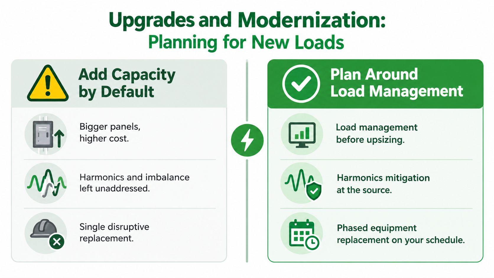
The default answer to a new electrical load is often “add capacity.” That answer can be correct, but it's not always the first or most economical move. A larger transformer or panel won't fix phase imbalance, harmonic heating, poor scheduling, voltage drop, bad connections, or a feeder that's constrained by a different part of the system.
Start with the actual operating profile
Before adding EV chargers, heat pumps, electric water heating, battery storage, or solar, establish the building's diversified peak demand. Review interval demand data, operating schedules, tenant use, HVAC staging, parking patterns, and emergency loads. Then map available capacity at the utility service, main switchgear, feeders, transformers, panels, and branch circuits.
Transformer losses illustrate why nameplate capacity alone can mislead. DOE transformer guidance reports that distribution transformers can account for approximately 3% to 5% of the power passing through them. The same guidance says selecting lower-loss equipment for the intended load factor can reduce transformer losses by approximately 11% to 29%, depending on output rating and utilization.
A lightly loaded transformer carries fixed core losses whenever it's energized. A heavily loaded transformer experiences rising winding losses because that component increases approximately with the square of per-unit loading, as described in DOE's transformer efficiency materials. That means the right capacity decision depends on the full load profile, including energized standby periods, not only the largest connected load.
Choose the least disruptive effective solution
- Use load management first: Scheduled EV charging, demand controls, and coordinated HVAC operation can reduce coincident peaks without immediately expanding the service.
- Address harmonics at the source: Non-linear loads may require power-quality logging, neutral evaluation, a suitable transformer design, or filtering. A bigger panel alone doesn't remove harmonic current.
- Replace rather than extend when condition demands it: A panel with damaged bus stabs, obsolete breakers, limited fault-duty capability, or poor spare-part availability may be a replacement candidate instead of a panel that just receives more breakers.
- Review feeder arrangements: A feeder reconfiguration or re-tap may solve a loading problem more cleanly than installing a new transformer, but only after voltage, protection, fault current, and code requirements are verified.
- Phase major replacements: Align switchgear replacement with planned outages, capital cycles, tenant turnover, and other building work. Temporary arrangements and switching plans must be engineered, documented, and performed by qualified personnel.
EV planning should include parking operations and tenant schedules. A property may not need every charger to deliver maximum power at the same moment. Managed charging can create capacity, but it needs a control strategy, clear ownership, reliable communications, and a fallback plan for abnormal operation.
Use commercial electrical system upgrades to connect the engineering decision with field conditions, equipment availability, and the disruption a replacement will create. The best upgrade is the one that addresses the limiting failure mode while leaving the property with a maintainable, documented system.
Safety, Code Compliance, and Operating Best Practices
Electrical safety becomes effective when the rules shape everyday work. NFPA 70E, the NEC, and local amendments provide the framework, but a safe facility still depends on current drawings, trained workers, controlled access, accurate labels, and disciplined switching.
Arc flash labels should match the equipment and the current study assumptions. PPE must match the labeled hazard and the task. Only qualified persons should perform work that requires electrical knowledge and training, especially where energized equipment is involved. Lockout/tagout must isolate the energy source, not merely turn off a local control switch.
Make the electrical room operationally reliable
Keep the single-line diagram current after tenant improvements, equipment replacements, feeder changes, and generator work. Standardize panel and breaker labels so a technician can identify the source, destination, and load without relying on outdated room names. Keep electrical rooms free of storage and restrict access to authorized personnel.
Selective coordination also deserves periodic review. If downstream and upstream protective devices aren't coordinated, a small fault may open a larger device and remove service from unrelated areas. Settings should reflect the installed equipment, available fault current, emergency source, and the current system configuration.
A written electrical safety program should define:
- Training requirements: Identify who can inspect, operate, test, and work on each equipment type.
- Switching procedures: Use written switching orders for complex operations, emergency transfer work, and planned outages.
- Contractor oversight: Confirm qualifications, scope boundaries, permits, labels, test records, and restoration steps.
- Inspection records: Store thermograms, test results, deficiency reports, corrective work orders, and closeout images together.
- Emergency response: Keep contact information, equipment access instructions, outage priorities, and utility coordination details available to the response team.
Spend the next dollar by risk
Age is a useful screening factor, but it isn't a complete priority system. A relatively old panel with clean inspections, available parts, and low consequence may deserve less immediate capital than a newer feeder serving an elevator, fire pump, data room, or major tenant.
Score each asset against criticality, condition, inspection findings, fault history, replacement lead time, operational consequence, and safety exposure. Then separate urgent corrective work from planned modernization. That approach gives owners a defensible reason for funding one repair or replacement before another.
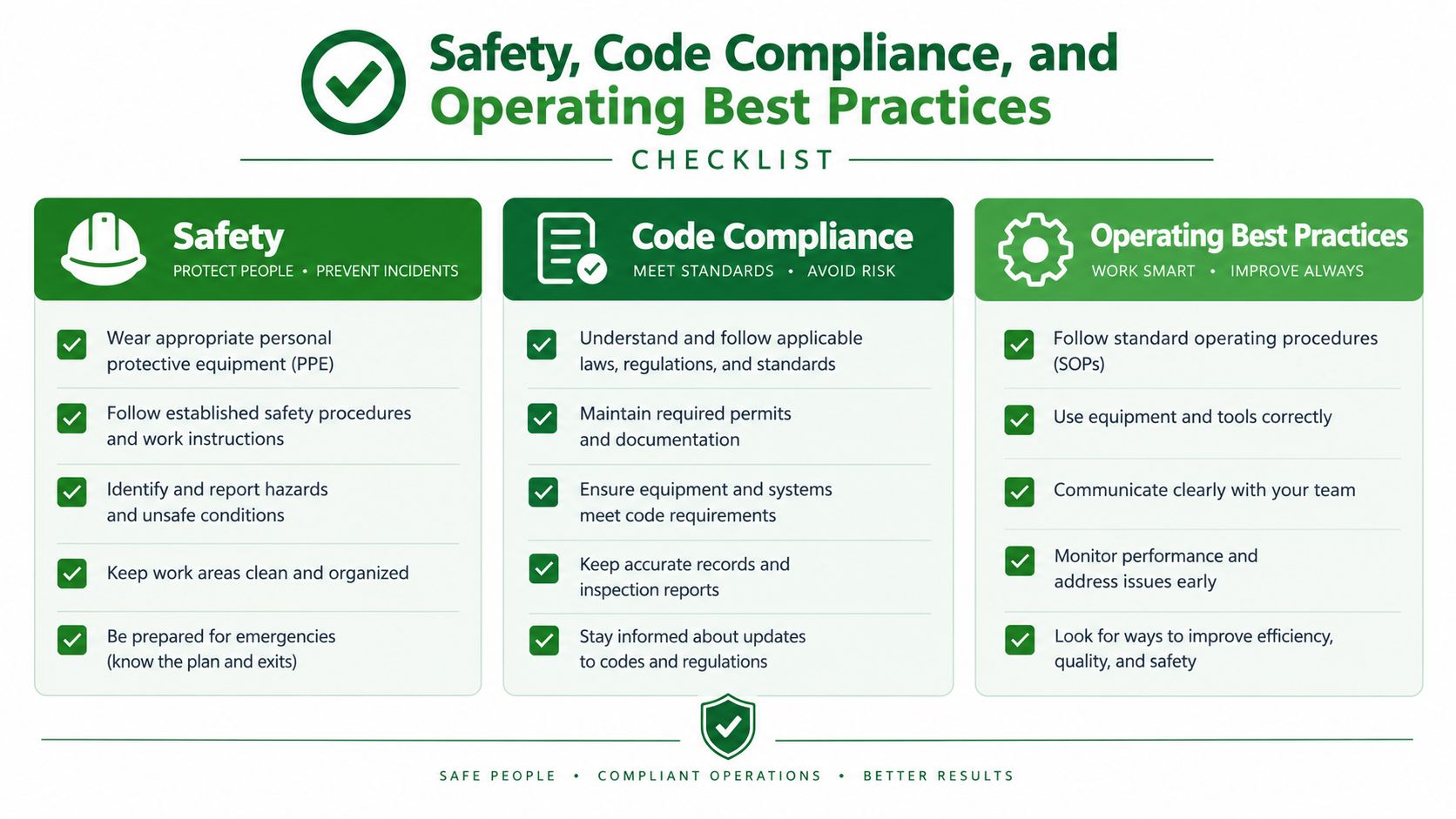
A property manager can use this short review to identify the next action:
- Documentation: Is the single-line diagram accurate in the field?
- Condition: Are recent inspection findings closed, assigned, and verified?
- Protection: Are breaker settings, labels, and coordination records current?
- Capacity: Can the service support planned electrification under realistic coincident demand?
- Safety: Are arc flash labels, PPE rules, qualified-person controls, and lockout/tagout procedures active?
- Response: Does the team know which assets can fail without taking down critical operations?
Access Electrical and Lighting provides commercial electrical distribution troubleshooting, panel and switchgear upgrades, infrared inspections, testing, emergency response, and EV charging installation for commercial, retail, office, and multifamily properties. If your building needs a documented condition assessment or a practical plan for repairs and new loads, contact Access Electrical and Lighting to discuss the equipment, operating risks, and next project step.