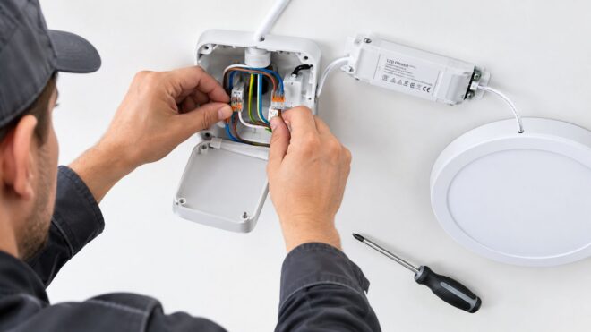
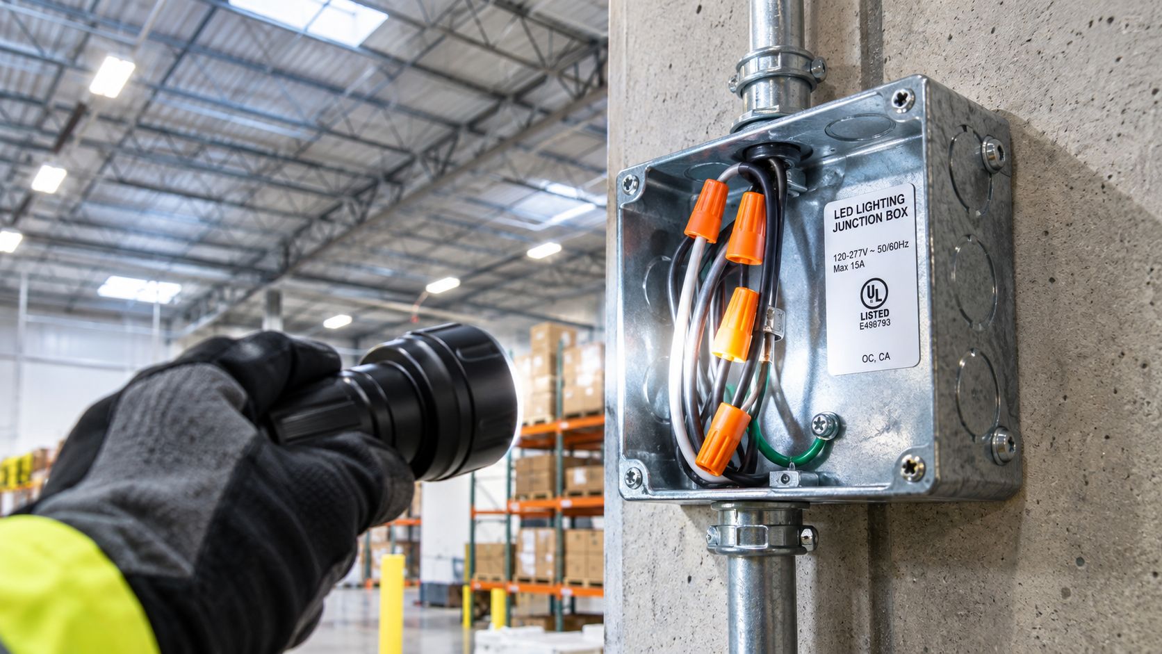
A high-bay retrofit can look finished until the inspector opens the box above the ceiling. The new LED fixture fits, the driver carries a listing, and the existing conductors reach the connection point. Then the project stalls because the box is inaccessible, undersized, poorly supported, or unsuitable for the environment.
A led lighting junction box is more than a container for wirenuts. It determines whether conductors have adequate space, whether grounding remains continuous, whether the luminaire is mechanically supported, whether moisture can enter, and whether future controls or driver repairs can be completed without damaging the installation. In Southern California commercial work, those decisions matter across warehouses, retail centers, multifamily properties, offices, canopies, and parking structures.
Why Junction Boxes Fail Inspection on LED Retrofits
A common Orange County retrofit starts with a legacy high-bay fixture and an existing ceiling box. The crew removes the old luminaire, installs the LED replacement, and discovers that the box is physically large enough for the splice. The wire sizes appear compatible, and the driver documentation is in the submittal package.
The inspector still flags the installation.
The problem usually isn't the LED wattage or the visible fit. The inspector is looking at the entire arrangement: accessibility, box volume, grounding, wiring method, environmental suitability, and mechanical support. A box that worked for an older fixture may not be suitable for a new luminaire that loads the box differently or uses a separate support method.
Practical rule: A box can be adequate for a splice and still be inadequate for the fixture, driver, controls, or location.
The 2011 National Electrical Code revision marked a significant change in how LED luminaires were addressed. Section 410.24 extended key box and wiring-method requirements to LED luminaires that are independently supported rather than supported by the outlet box. In that arrangement, the branch-circuit connection must use a raceway or an approved cable type such as MC, AC, or NM cable. A surface-mounted LED luminaire over a concealed outlet box also needs openings that allow access to branch-circuit wiring inside the box when the fixture isn't supported by that box. The NEC history and LED luminaire requirements are discussed by EC&M.
The failures behind the red tag
Inspectors commonly find one or more of these conditions:
- The box is concealed. A splice or termination isn't serviceable if the finished ceiling, insulation, or fixture prevents access.
- The fill calculation is missing. Counting visible insulated wires without accounting for grounds, clamps, devices, or fittings produces an incorrect result.
- The fixture has no approved support path. Physical contact with a box doesn't automatically make the box suitable to carry the luminaire.
- The enclosure doesn't match the location. An indoor dry-location box may not belong in a damp parking structure, canopy, exterior site-lighting assembly, or pole base.
- Control conductors are mixed without a plan. Line-voltage conductors and Class 2 control wiring can create separation, identification, and serviceability problems.
- The cover compresses the splice. A cover that installs only by forcing crowded conductors inward is a warning sign, even when the stamped volume appears adequate.
The fixture listing matters, but it doesn't erase the requirements for the box, wiring method, support, or installation instructions. On a retrofit, the correct question isn't “Will this LED fixture turn on?” It's “Does this complete installation remain accessible, supported, protected, documented, and serviceable?”
How to Choose the Right LED Lighting Junction Box
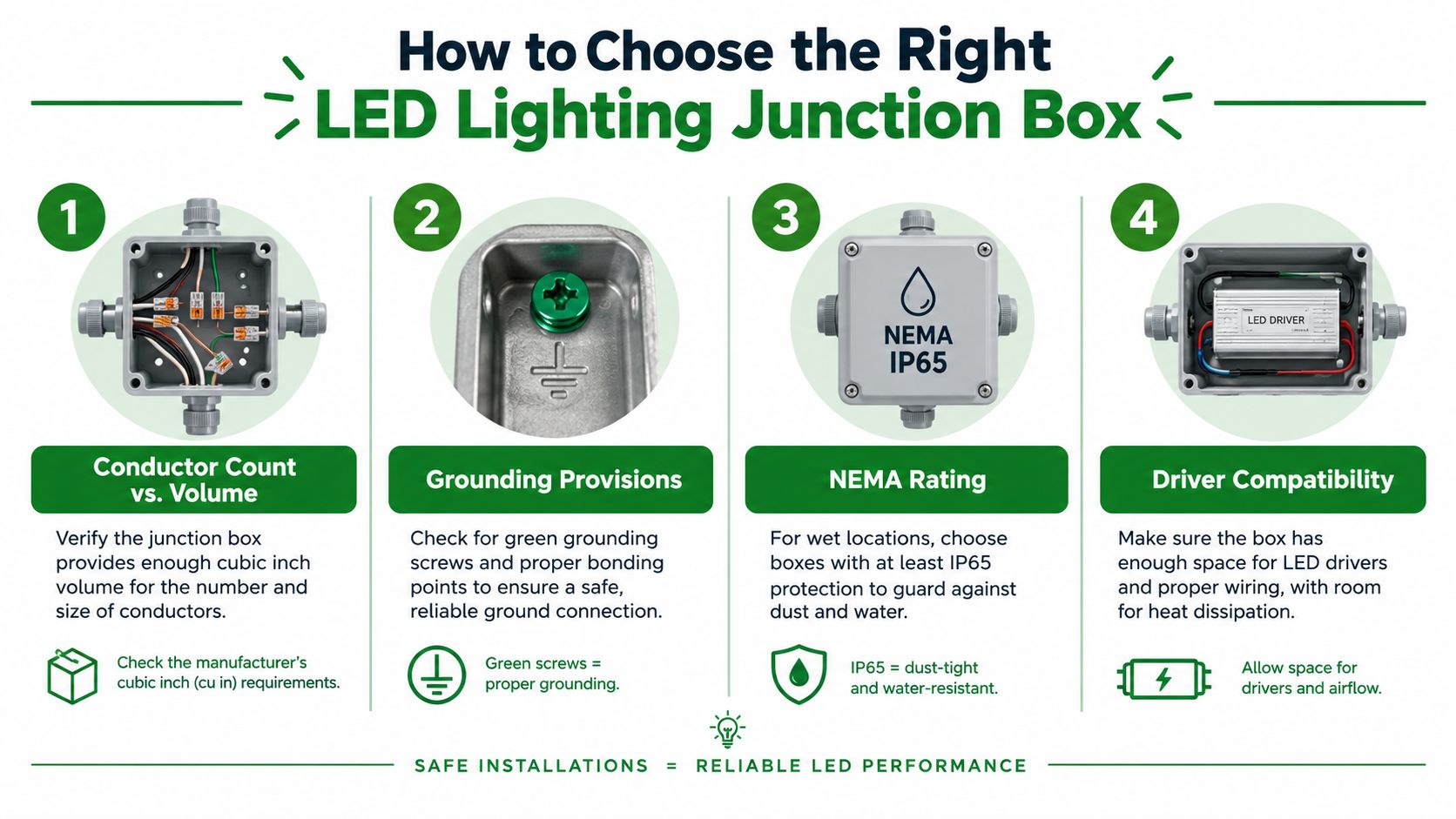
Choose the enclosure from the installation conditions inward, not from the LED label outward. The key inputs are volume, grounding, accessibility, environmental rating, and listing status. Each one answers a different question, so passing one check doesn't compensate for failing another.
Start with volume and conductors
Box volume follows the conductors and components inside the enclosure. Record the conductor count and American Wire Gauge, then account for insulated conductors, grounding conductors, internal clamps, devices, fittings, and other installed parts. The manufacturer's marked volume must meet or exceed the calculated fill under the applicable NEC requirements.
A compact box may appear efficient, but it leaves less room for proper splicing and future troubleshooting. An oversized box generally gives the crew better working space and reduces the chance of damaged insulation, crowded connectors, or a cover that won't seat correctly.
Confirm the grounding path
The box needs a reliable grounding arrangement appropriate to the wiring method and listed components. Check for the grounding means specified by the box and luminaire instructions, and verify continuity before closing the enclosure. Don't assume a metal box is grounded just because metal is present. The bonding method, fittings, cable armor, grounding conductors, and device connections all need to work together.
Match the enclosure to the location
A dry indoor office installation has different enclosure needs from an exposed canopy or parking structure. Basic NEMA 1 protection can commonly serve dry indoor conditions, while damp or wet locations require a more protective NEMA or ingress-protection rating appropriate to the exposure. Parking structures, exterior site lighting, pole bases, service areas, and canopies deserve particular scrutiny because water, condensation, dust, and temperature changes can attack connections over time. This enclosure-selection guidance covers box fill, environmental classifications, and listing considerations.
Use the enclosure, cover, gasket, hubs, and fittings as a coordinated assembly. A weather-rated box fitted with an unsuitable cover or an unsealed entry isn't a weatherproof installation.
Verify listing and instructions
Look for the applicable UL or ETL listing on the enclosure or luminaire assembly, then read the installation instructions. NEC Section 110.3(B) requires listed equipment to be installed according to its instructions. That can affect permitted mounting, conductor types, driver placement, cover use, support methods, and environmental limits.
| Decision point | Field question |
|---|---|
| Volume | Does the marked box volume meet the documented fill calculation? |
| Grounding | Is the grounding and bonding path complete for the box and fixture? |
| Accessibility | Can a technician reach the splices and driver without destructive removal? |
| Environment | Does the enclosure and cover match dry, damp, or wet exposure? |
| Listing | Are the box, fittings, luminaire, and installation method used as instructed? |
For retrofit planning, review the commercial LED retrofit installation services as one example of the broader inspection questions that arise when existing boxes are reused.
Performing Box-Fill Calculations Before Energizing
A retrofit can pass the wiring inspection and still fail at the box. The arithmetic is simple, but missed conductors, clamps, grounding allowances, or fittings make the documented volume wrong. NEC Article 314.16 requires the box volume to meet or exceed the calculated fill. NEC 314.16 separates allowances for conductors, clamps, devices, fittings, and grounding conductors, so the count must cover the complete assembly.
Use a four-part field check
Before energizing a commercial LED fixture, record the actual enclosure and work through the items that affect the calculation:
- Count every insulated conductor that enters, terminates, is spliced, or passes through the box.
- Add the applicable grounding-conductor allowance, using the largest equipment-grounding conductor present.
- Add internal clamp, device, support, and fitting allowances required by the box and installation.
- Apply the cubic-inch allowance for the largest conductor, then compare the total with the manufacturer-marked box volume.
Photograph the volume marking before the fixture or cover hides it. Record conductor sizes, cable entries, grounding conductors, internal clamps, fittings, and the selected cover. That documentation gives the foreman and inspector a clear basis for the installation.
A 14 AWG example
Consider a basic two-cable splice. One 14/2 cable feeds the box, and another 14/2 cable continues to the next fixture. The insulated-conductor count is four:
- Feed hot and neutral
- Continuation hot and neutral
The grounding group adds one allowance, and an internal cable clamp adds another. For 14 AWG conductors, the standard allowance is 2.00 cubic inches per volume unit. The four insulated conductors, one grounding allowance, and one clamp allowance produce six conductor-equivalent units. Six units multiplied by 2.00 cubic inches require 12.00 cubic inches before adding any device or fitting, as shown in EC&M's box-fill discussion of the 14 AWG example and its 12.00 cubic-inch result.
The example shows why a box can look roomy and still fail the calculation. A replacement luminaire may add a driver connection, control conductors, or fittings, changing the count even when the original splice remains unchanged.
Check the physical fit
The marked volume is only one part of the decision. Wirenuts should not press against the cover, conductors should not be sharply folded over a fitting, and the cover should install without excessive force.
A calculation that passes on paper does not justify a mechanically crowded splice.
Use a larger enclosure when the location allows it. Extra room supports cleaner routing, gives technicians better access, and reduces the risk of forcing connectors into a box that barely meets the minimum. For connector selection, document the conductor combination and follow the manufacturer's capacity information, including guidance on blue wire nut capacity and conductor combinations.
Before energizing, compare the calculation sheet with the installed box. A change from MC cable to conduit, an added control lead, a larger grounding conductor, or a different fixture whip can invalidate the original count. The junction box is the point where those wiring, control, and inspection decisions meet, so update the calculation whenever the system changes.
Thermal, Control, and Serviceability Considerations
An LED installation can be electrically compliant and still be poorly arranged for heat. The diodes may operate efficiently, but the driver, connectors, and enclosed wiring can experience damaging temperatures inside a tight cavity, near insulation, beneath a hot roof, or inside a compact enclosure.
Junction temperature affects LED performance characteristics including efficacy, forward voltage, chromaticity, and product life. That makes thermal planning part of junction-box selection, especially when the driver sits in or immediately beside the box. A cool-looking fixture doesn't prove that the driver compartment is cool enough.
Treat the box as a thermal node
Start with the driver instructions. Check permitted mounting positions, ambient limits, required clearances, and whether the driver may be enclosed. Then inspect the actual installation, not just the submittal drawing. A warehouse roof cavity, rooftop penthouse, parking structure, or insulated ceiling can produce conditions that differ substantially from a controlled test environment.
Avoid packing the enclosure with unnecessary conductor length. Don't bury the driver where a technician can't inspect or replace it. Keep insulation and other heat-retaining materials out of spaces that the manufacturer identifies as requiring clearance.
A practical thermal review asks:
- Is the driver enclosed when the instructions require ventilation or a specific mounting surface?
- Can a technician reach the driver without cutting the ceiling or dismantling adjacent equipment?
- Are splices positioned away from obvious heat sources?
- Could future controls or added wiring crowd the enclosure?
- Is there a documented way to investigate a recurring failure?
Keep controls deliberate and identifiable
Modern commercial lighting often adds 0–10 V or digital-control wiring, occupancy sensors, daylight sensors, emergency controls, or networked components. Those circuits need a planned path, clear identification, and separation consistent with the applicable wiring rules and manufacturer instructions. Don't use leftover box space as an excuse to mix conductors without reviewing their classifications and required separation.
Control wiring also changes service work. A fixture can illuminate normally while its sensor, dimming input, or emergency-control connection is wrong. Leave enough room to inspect terminations and label the conductors so the next technician doesn't have to guess.
DesignLights Consortium SSL V6.0 materials describe broader dimming, control, and reporting requirements, with closer integration between controllable solid-state lighting and networked-lighting-control qualification planned for 2026. The DLC material outlines this direction for controllable products and networked controls. That makes future compatibility a practical design concern rather than a distant specification issue.
The best box arrangement passes today's inspection and leaves a technician a safe, cool, clearly organized place to work later.
Mounting, Weatherproofing, and Field Verification
Installation quality shows up at the box entries, cover, support points, and documentation. A surface-mounted luminaire, a concealed box, and a raised pole fixture each create different mechanical and environmental demands. Start by confirming what supports the fixture, then confirm what protects the conductors.
For a surface-mounted LED luminaire installed over a concealed outlet box, verify whether the fixture is supported by that box. If it isn't, the branch-circuit wiring still needs an approved connection method, and the luminaire needs access openings that allow wiring access inside the box where the applicable rule requires them. Don't let the fixture's trim hide an inaccessible connection.
Build the enclosure as an assembly
Use listed fittings that match the box, cable, conduit, and environmental rating. Tighten hubs and connectors according to manufacturer instructions, protect cable entries from abrasion, and provide strain relief where the fixture or whip can move. A gasketed cover only works when the cover, gasket, and box face align correctly.
In damp or wet locations, inspect the entire water path:
- Box and cover: Confirm that both carry the required environmental rating.
- Entries: Use compatible hubs, connectors, and seals rather than improvised caulk around a poor-fitting opening.
- Gaskets: Keep the gasket flat, clean, and undamaged.
- Drainage: Follow the enclosure and fixture instructions for drainage or drain fittings.
- Thermal cycling: Allow fittings and sealants to accommodate repeated expansion and contraction.
- Strain relief: Prevent movement from transferring force to splices or driver leads.
Parking structures, canopies, exterior site lighting, and pole bases deserve a closer inspection than an indoor office. Water can arrive from rain, washdown, condensation, or migration along a cable. Review the applicable commercial outdoor lighting installation practices when the retrofit crosses from an interior dry space into an exposed assembly.
Verify before the cover goes on
A short field checklist prevents a long callback. Photograph the open box, the volume marking, the grounding connection, and the finished cover. Then compare the installation with the approved submittal and instructions.
- Confirm the conductor sizes and physical count.
- Verify that the box-fill calculation matches the installed conductors and fittings.
- Inspect splices for proper stripping, connector engagement, and available working space.
- Confirm grounding continuity for the box, luminaire, and wiring method.
- Check that the support method matches the fixture and box listing.
- Verify control conductors are identified and separated as required.
- Inspect the gasket, cover, entries, and seals in damp or wet locations.
- Label the driver and controls where future service requires identification.
Don't close a box that you haven't photographed and checked against the actual field condition. Documentation helps the inspector understand the work and gives the property manager a useful maintenance record.
Common Mistakes and How to Avoid Them
The most expensive assumption on an LED retrofit is that wattage and physical fit determine compatibility. They don't. A legacy box may accept the conductors and still be unsuitable for the luminaire's support method, the driver's heat, the location's moisture, the emergency-lighting circuit, or a later controls upgrade.
The mistakes that keep recurring
Treating the box as a simple splice enclosure ignores support, accessibility, listing requirements, and the relationship between the box and luminaire. Use the box as part of the complete installation, not as an isolated container.
Skipping box-fill documentation creates an inspection problem even when the splice looks tidy. Count grounds, clamps, devices, and fittings, then compare the calculation with the marked volume before the cover disappears.
Ignoring thermal accumulation assumes that LED efficiency eliminates heat concerns. Review driver instructions, mounting conditions, insulation, and service access before placing a driver in a compact or enclosed space.
Overlooking mixed line-voltage and Class 2 wiring leaves control conductors difficult to identify and service. Confirm circuit classifications, separation, routing, and manufacturer requirements before adding sensors or dimming leads.
Using a cover that compresses the splice turns a technically acceptable volume into a poor physical installation. Select a deeper or larger listed enclosure when the conductors won't lie naturally under the cover.
Reusing undocumented legacy wiring transfers unknown problems into the new lighting system. Trace the circuit, confirm conductor condition and grounding, identify abandoned conductors, and record what remains in the enclosure.
Ask one question before reusing an existing box: Is it merely a legal splice enclosure, or is it also rated and mechanically suitable for the fixture, driver, controls, and environment?
The same question applies to multifamily corridors, retail ceilings, parking facilities, and emergency fixtures. A listed LED assembly doesn't make an unsuitable box acceptable, and a box that passed a previous installation isn't automatically appropriate for today's retrofit.
Access Electrical and Lighting provides commercial LED retrofit installation, junction-box inspection, parking and site-lighting work, controls, emergency lighting, and documented electrical testing for Southern California properties. If your retrofit needs a box-fill review, thermal and control coordination, or field verification before inspection, contact Access Electrical and Lighting to discuss the installation.