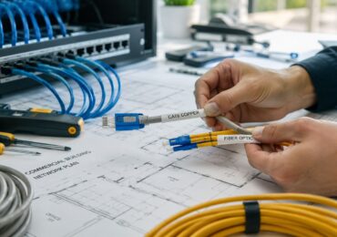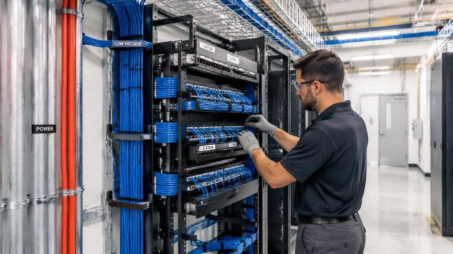
A ceiling grid is coming down in an occupied office, a retail tenant needs another camera, or a facility manager has just discovered that nobody can identify the bundle feeding a failed access-control reader. The cables are there, but they're tangled with abandoned runs, pressed against power, and packed into a pathway with no room left for the next project. That's when a simple installation becomes downtime, rework, and an inspection problem.
Commercial low voltage cable management isn't cable decoration. It's the discipline that protects signal performance, fire-resistance assemblies, service access, and future expansion. The work has to account for copper and fiber, horizontal runs and backbone links, telecommunications rooms, separation from line voltage, and the documentation an owner will need long after the installer leaves.
Why Low Voltage Cable Management Matters in Commercial Properties
A failed access point, offline camera, or dark digital sign often leads to the same discovery above the ceiling: communication cable is draped across electrical raceways, crushed by another trade, or packed into a tray with no capacity left. The system may have worked at turnover, but the installation leaves little margin for troubleshooting, inspection, or the next tenant improvement.
Poor management creates technical and compliance problems that may stay hidden until testing or service. Tight bends can deform copper conductors, while excessive pulling force changes cable geometry and reduces performance. Routing communication cabling too close to power increases electromagnetic interference risk. An unsealed penetration can compromise a rated wall or floor and create firestopping liability for the contractor and owner.
The infrastructure behind daily operations
Commercial properties rely on low-voltage pathways for structured data cabling, access control, video surveillance, audio-visual systems, digital signage, building automation, and life-safety communications. Low-voltage wiring is generally defined as 50 volts or less, and its routing, grounding, and certification requirements differ from higher-voltage electrical systems. Provision's low-voltage scope guidance explains why these systems belong in a structured cabling design, rather than being added as loose wiring at the end of construction.
Category 6A is widely treated as the current commercial standard because it supports 10-gigabit Ethernet up to 100 meters. Category 6 is commonly associated with 1 Gbps up to 100 meters, while Category 5e is increasingly considered obsolete for new commercial work. Those ratings depend on the installation. Bend radius, pulling tension, separation, termination quality, and pathway congestion all affect whether the cable performs as specified.
Floorplate planning affects cable access
Telecommunications rooms also affect long-term operating cost. Industry guidance commonly places these rooms every 3,000 square feet in commercial buildings. The measurement matters less than the planning principle. Large floorplates, long horizontal runs, and multiple service zones can make an inconveniently located room expensive to maintain and can force technicians into occupied areas for routine work.
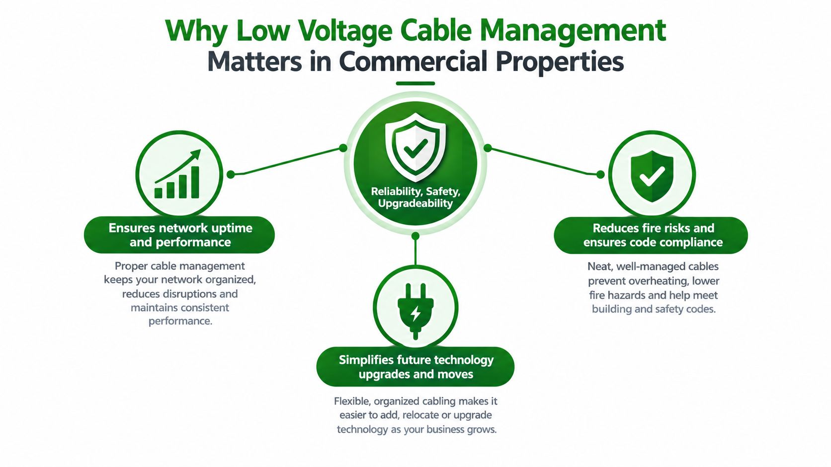
Good low voltage cable management provides accessible routes, identifiable endpoints, protected pathways, and spare capacity for future work. It also gives the owner a defensible installation when an authority having jurisdiction reviews penetrations, cable types, separation, support, and fire-resistance measures. Neatness helps, but reliability, safety, and upgradeability are the outcomes worth paying for.
Planning Pathways and Separation Before You Pull Cable
The cable that costs least to correct is the cable still on the spool. Before opening a box of Cat6A or fiber, confirm each run's origin, destination, pathway, required space, and relationship to the other trades using that route.
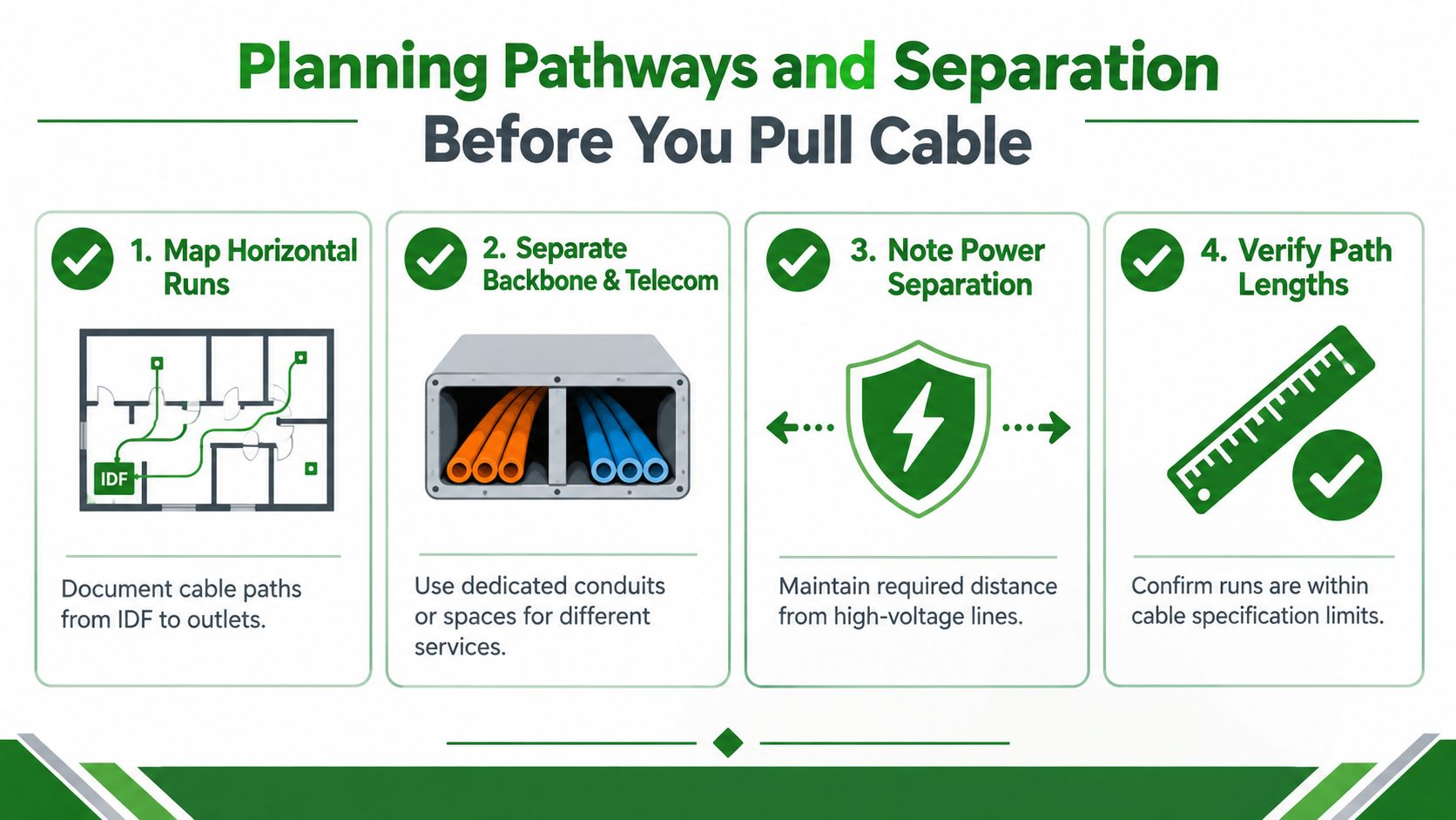
Begin with the floor plan and riser diagrams, then verify the design against the ceiling space. Mark horizontal runs from each telecommunications room to outlets, cameras, access points, displays, controllers, and other devices. Identify backbone links between rooms, floors, and equipment spaces. A short route on paper can become inaccessible after ductwork, lighting, sprinkler piping, and mechanical equipment occupy the ceiling.
Make separation a layout decision
Communication cabling needs a defined pathway, not whatever electrical space remains available. Keep low-voltage routes separate from line-voltage conductors with dedicated conduit, tray compartments, or clearly separated raceway spaces where the design requires them. Power conductors can introduce electromagnetic interference, while shared routes make fault-finding and later changes harder, even when the initial system appears to work.
Plan crossings with the electrical contractor. A crossing may be unavoidable, but a long parallel run beside power creates a different exposure. Review applicable electrical and structured-cabling requirements, equipment manufacturer instructions, and project specifications before installation. Separation also affects firestopping decisions, because crowded or mixed penetrations can complicate approved sealing methods and increase inspection liability.
Planning rule: Separate services on the drawing before the field crew has to separate them in a crowded ceiling.
Check capacity before ordering labor
Verify conduit and tray capacity against the actual cable types, outside diameters, pulling routes, and termination needs. For data cabling, industry guidance commonly uses a 40% maximum conduit fill target, leaving room for heat dissipation and future additions. Megaservices' low-voltage cabling guidance places pathways and separation first, capacity verification next, then pulling, labeling, and testing.
Do not design only around the issued cable schedule. Commercial buildings add cameras, wireless access points, signs, occupancy controls, and tenant technology. Show spare capacity on the drawings, and reserve usable pathway space instead of assuming the installer can force another bundle through later.
A pre-pull review should confirm:
- Pathway ownership: Identify routes for data, security, audio-visual, controls, and backbone cabling.
- Power coordination: Review parallel runs and crossings with the electrical contractor before work starts.
- Capacity: Check conduit, tray, and sleeve space using real cable dimensions.
- Access: Confirm reach to pull points, junction locations, racks, and patch panels.
- Run limits: Verify planned lengths against cable and system specifications.
- Expansion space: Reserve capacity for additions rather than filling every opening.
A qualified experienced low-voltage cabling contractor can review route drawings, separation, spare capacity, and field conditions before a crowded ceiling turns a design decision into rework.
Routing Protecting and Supporting Low Voltage Cabling the Right Way
A cable can pass through an approved pathway and still fail in the field. Pulling too hard, crushing jackets with ties, or leaving unsupported bundles above a finished ceiling creates faults that may surface during certification or after access is gone. Installation quality depends on controlled handling from the pull point to the rack, outlet, device, or panel.
Use the cable manufacturer's bend-radius requirement as the controlling document. For Cat6 and Cat6A-type copper, installation guidance often uses a bend radius of about four times the cable's outside diameter, although the exact value depends on the cable datasheet and applicable standard. Sharp bends, overfilled pathways, and contact between power and communication cabling remain common sources of damage and rework.
Pull with control, not force
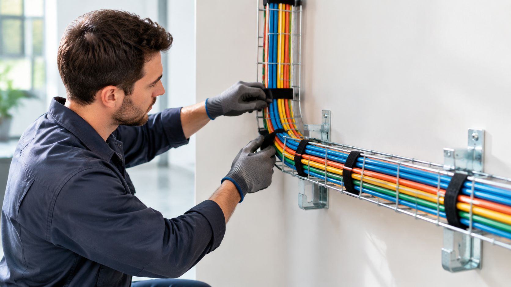
A proper pull uses a rated pulling method, a clear route, and communication between the person feeding cable and the person receiving it. Do not drag a bundle across sharp metal edges or allow it to kink at a pull box. Keep the jacket intact, control tension, and use hook-and-loop fasteners where they offer better control than tight plastic ties.
Choose the support system for the space and the service conditions:
- J-hooks: Suitable for accessible office ceilings when the route is open and the cable is protected from physical damage.
- Cable tray: Useful in organized corridors, equipment rooms, and larger bundles requiring a defined support system.
- Conduit: Provides physical protection and a controlled route, but requires careful planning for fill, pull points, and bends.
- Raceway: Protects exposed cable while providing a finished appearance in retail or public-facing areas.
- Ladder tray or wire basket: Helpful around racks and equipment rooms where technicians need access for dressing and later additions.
Use an approved support method for the application and project requirements. Cable should not rest on ceiling tiles, sprinkler piping, ductwork, light fixtures, or unrelated equipment. In an active retail corridor, coordinate above-ceiling work before the store reopens. In an office, keep service loops controlled and clear of access panels. In a multifamily riser, protect vertical runs from abrasion and maintain support at transitions.
Match the cable to the space
Cable selection must follow the environmental and code conditions along the route. Plenum spaces and concealed areas can impose flame and smoke requirements that differ from ordinary occupied spaces. Do not substitute an available cable without confirming its rating, jacket type, and approval for that location.
Fiber requires separate handling rules. Protect connectors from contamination, follow the fiber manufacturer's bend limits, and keep heavy copper bundles off fiber. Cat6A also needs additional room at racks and patch panels because its larger construction makes tight dressing more damaging.
Leave usable capacity in the support system for service work and future additions. A pathway packed during the first installation turns every later change into a pullout, reroute, or ceiling repair.
The installation that survives inspection looks deliberate. Bundles follow the route, supports carry the load, service loops stay controlled, power remains separated, and no cable is forced into a pathway that was undersized from the start.
Labeling Documentation and Testing That Prevents Future Headaches
A cable that works today but can't be identified tomorrow is an incomplete installation. During a tenant move, a failed camera, or a network change, the technician needs to locate the correct run without opening ceilings or tracing every bundle by hand.
Two labeling methods are common. One relies on handwritten tags and installer memory. The other uses a consistent identifier tied to the telecommunications room, patch-panel position, outlet, device, and drawing set. The first approach feels faster during rough-in. The second survives turnover, staff changes, and service calls.
Put the same identity at both ends
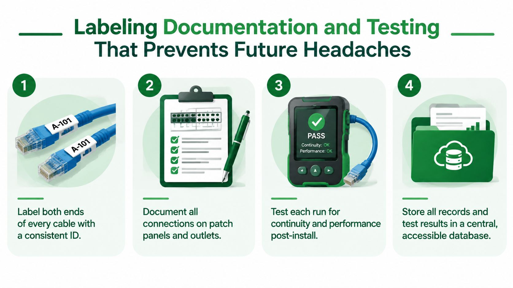
Label both ends of every permanent cable before the pathway disappears. Use durable labels that remain legible in the room and match the project's naming convention. Patch panels, racks, outlets, camera locations, control panels, and telecommunications rooms should use the same language.
A useful record connects four items:
- Cable ID: The identifier printed at both ends.
- Origin and destination: The room, rack, panel, outlet, or device served.
- Path information: The tray, conduit, riser, sleeve, or zone used.
- Verification record: The test result, date, technician, and tester used.
Compare documentation that holds up
Paper notes can work for a small, stable installation, but they're easy to misplace and difficult to search. A spreadsheet improves organization, yet it can become unreliable when several people update it without version control. A central project record tied to as-built drawings and exported test results gives the maintenance team a more dependable handoff.
Testing should happen before ceilings and walls close. Copper testing may include continuity, wiremap, length, and performance certification appropriate to the cable category and system specification. Fiber testing requires the instruments and procedures suited to the installed fiber system. The exact acceptance criteria come from the project documents, cable manufacturer, and applicable standard.
Service reality: A test result without a matching cable ID is evidence for a cable nobody can find.
Don't wait for a problem to discover missing records. Store test files, marked-up drawings, firestop documentation, panel schedules, and change records in a location the owner can access. During inspection, the team can produce evidence instead of reconstructing the installation from memory. During maintenance, a technician can move from the label to the drawing to the test record in a controlled sequence.
Firestopping and Code Compliance for Cable Penetrations
The most expensive low-voltage mistake often looks insignificant. A technician passes a bundle through a rated wall, leaves the opening loosely packed, and assumes the cable's low voltage classification makes the penetration exempt. It doesn't.
Penetrations through rated walls, floors, fire separations, plenums, and service spaces require a code-compliant treatment. Canadian building-code guidance states that penetrations through fire separations must use a tested firestop system matched to the required barrier rating. The same guidance also addresses cable and raceway selection in plenums and concealed spaces, including FT-4 and FT-6 conditions in specific construction situations. The National Research Council Canada guidance on firestopping and cable penetrations is a useful reminder that the pathway and the opening must be evaluated together.
Treat every opening as a life-safety detail
The installer needs to classify the assembly and space, select an approved cable or raceway, install the tested firestop system, and record what was used. The sealant, backing material, sleeve, dam, and cable arrangement must be compatible with the listed system. A generic caulk applied after the fact isn't a substitute for an approved assembly.
The issue also applies to low-voltage penetrations under IRC 2024, where rated assemblies require approved firestop materials and exterior wall or top-plate penetrations need weather sealing and fire-blocking. The IRC 2024 guidance on Class 2 penetration firestopping highlights a detail generic cable-management checklists often miss.
Before closure, document:
- Assembly type: Record the rated wall, floor, ceiling, or top-plate condition.
- System selection: Identify the tested firestop system and compatible products.
- Cable arrangement: Note sleeves, bundle size, raceway type, and future pathway provisions.
- Inspection evidence: Photograph the completed work and retain product information.
- Weather protection: Seal exterior penetrations against moisture as well as fire spread.
A failed firestop inspection can force a crew to reopen finished work, remove cable, correct the opening, and restore the assembly. Property teams should treat electrical code compliance support as part of the low-voltage scope, not as a final cleanup task.
Maintaining and Future Proofing Your Low Voltage Cable Plant
A commercial cable plant changes continuously. Tenants add devices, security teams replace cameras, wireless coverage expands, and building controls become more connected. A pathway that was acceptable at turnover can become difficult to service if nobody controls additions, removes abandoned cable, or updates the records.
Start with a repeatable inspection routine. Look for unsupported cable, damaged jackets, tight ties, blocked access, water exposure, pathway congestion, and new power runs placed beside communication cabling. Check racks and patch panels for strain, poor labeling, and service loops that obstruct ports or airflow.
Reserve room before the next project
Future-proofing is physical, not just technological. Independent guidance recommends at least 30% spare pathway capacity and conduit fill below 40% to reduce rework during future pulls, as described in this structured cabling and data-center pathway guide. Those figures should be applied to the pathway design, not used as permission to overfill an existing route.
Modular trays, accessible raceways, spare sleeves, and planned pull points make expansion easier. Pre-terminated or modular systems can reduce field termination work in suitable environments, but they also require accurate measurements, protected handling, and a clear replacement strategy. Choose the method that fits the building's access, service model, and future change pattern.
PoE devices, smart patch panels, cloud-managed systems, and automated monitoring are changing what owners expect from the cable plant. The more devices a building supports, the more valuable clean records and accessible pathways become. Commercial electrical maintenance planning can incorporate low-voltage inspections alongside broader facility maintenance, including documented diagnostics where appropriate.
Use a simple upkeep cycle
- After every project: Update as-builts, labels, test files, and firestop records.
- During routine inspections: Check supports, separation, pathway loading, and visible damage.
- Before tenant work: Review spare capacity and reserve routes before approving additions.
- When faults recur: Test the installed segment instead of repeatedly replacing devices.
- After alterations: Photograph changed pathways and remove or identify abandoned cable.
The property team doesn't need to predict every future device. It needs a cable plant that remains accessible, documented, separated, protected, and expandable. That's the difference between a one-time pull and infrastructure that keeps serving the building.
Access Electrical and Lighting provides commercial low-voltage installation, testing, maintenance, and repair for copper and fiber cabling, automated controls, distributed audio, digital signage, video walls, and related systems. Visit Access Electrical and Lighting to discuss pathway planning, compliance details, documentation, and ongoing maintenance for your commercial, retail, office, or multifamily property.