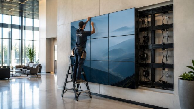
The ribbon-cutting is tomorrow morning. In the corporate lobby, a 3×3 LCD video wall is mounted, the content is loaded, and the commissioning team is still searching for the missing dedicated circuit. Behind the finished glass and polished millwork, nobody planned enough room to service the displays or a clean pathway for the final conduit run.
That situation is common because the panels attract all the attention. The visible screens may represent only part of the work. Structural support, dedicated power, grounding, signal distribution, control equipment, ventilation, access panels, and commissioning determine whether the wall performs reliably after the launch event.
A well-designed video wall installation starts weeks before equipment arrives. The current commercial market reflects how substantial this work has become. One industry estimate values the global video wall market at USD 11.81 billion in 2025, with a projection of USD 23.06 billion by 2031 at a 11.79% CAGR, while Asia-Pacific represents 37.92% of 2025 revenue in that estimate (Mordor Intelligence's video wall market estimate). For electrical contractors, that growth translates into continuing demand for circuits, raceways, mounting structures, controls, and service planning.
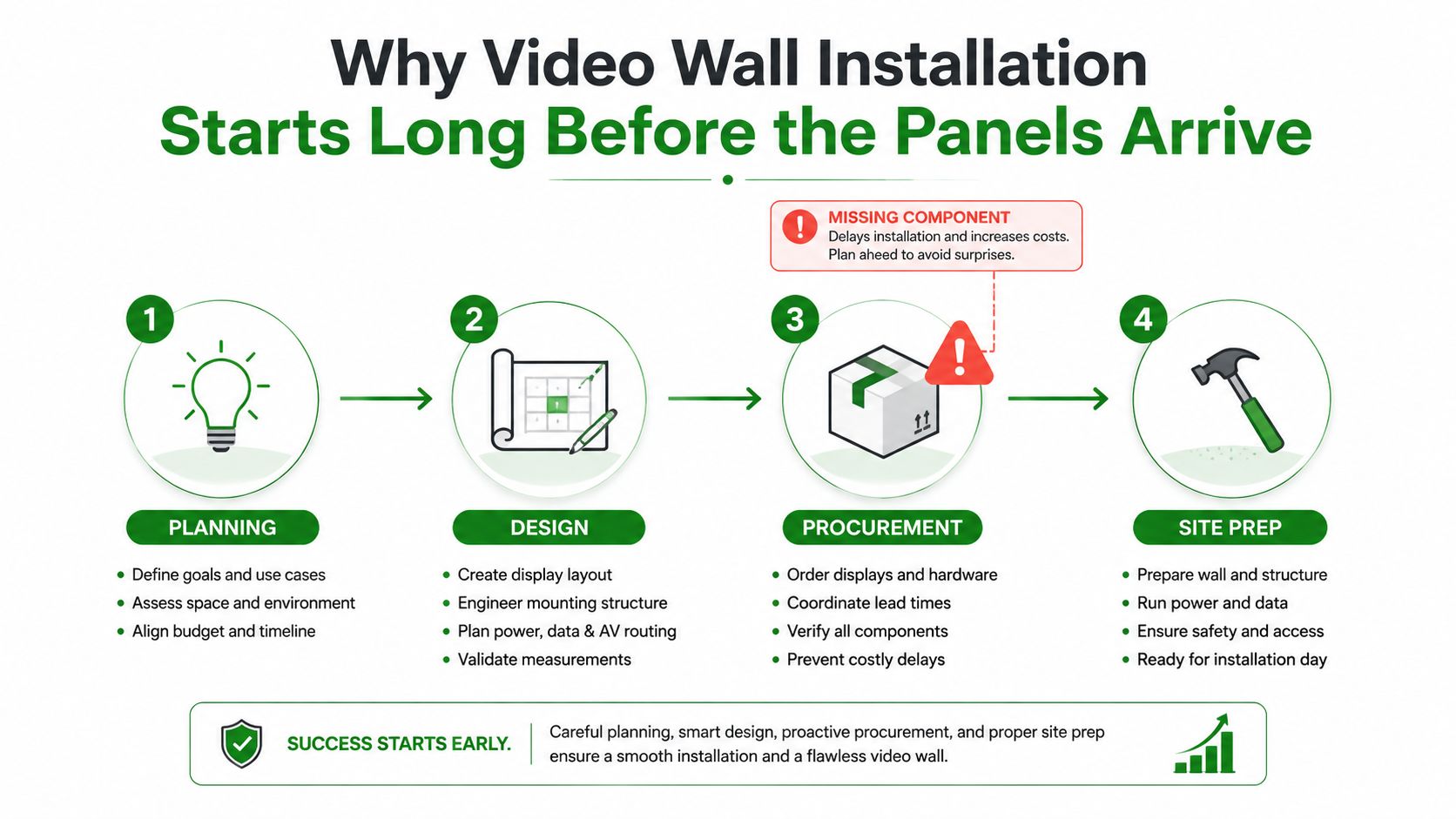
Why Video Wall Installation Starts Long Before the Panels Arrive
At the Irvine lobby, the missing 20-amp circuit wasn't a small punch-list item. The electrical panel had limited spare capacity, the nearest pathway was on the wrong side of a finished wall, and the glass feature wall left little room for a late conduit adjustment. The AV team could configure the processor, but the display couldn't be signed off until the electrical infrastructure was safe, dedicated, and documented.
That failure usually begins during design, not installation. The general contractor, electrician, AV integrator, millwork fabricator, and structural engineer need a shared drawing that identifies wall construction, mounting rails, panel dimensions, equipment racks, circuits, control locations, and service clearances. If those details remain in separate emails, each trade works from a partial picture.
The expensive problems hide behind the display
Late planning creates predictable trouble:
- Blocked service access: A flush wall may look clean, but technicians can't replace a power supply if the design leaves no front access, removable trim, or rear working space.
- Trapped heat: LED cabinets and processors need a planned path for heat to leave the enclosure. Decorative millwork can turn a display cavity into an oven.
- Unusable pathways: A finished lobby may have no conduit route from the source, rack, or control station to the wall.
- Controller mismatches: Firmware, resolution, EDID, and HDCP settings can prevent a source from handshaking correctly even when every cable is connected.
- Structural rework: Drywall without adequate blocking may require opening the wall or installing a freestanding support frame.
Projects run smoothly when the trades coordinate before procurement. The electrician confirms panel capacity and raceways, the structural team verifies the mounting surface, and the AV team provides the actual equipment schedule instead of a generic display cut sheet. That coordination turns the installation into a controlled sequence rather than a race to conceal mistakes before opening day.
Field rule: If nobody can point to the circuit, grounding method, signal pathway, and service access on the drawings, the wall isn't ready to order.
Surveying the Site and Reading the Room
A useful site survey starts with the wall, not the display model. Identify whether the surface is drywall over wood studs, concrete masonry, structural concrete, or steel framing. Each condition changes the anchor type, rail design, load distribution, and inspection requirements.
Drywall alone isn't a mounting structure. The survey should locate studs, blocking, embeds, and concealed utilities before anyone drills. A rail or unistrut system can distribute load across multiple structural members, but it can't compensate for missing support or a wall that wasn't designed to carry the assembly.
Work from the audience backward
Next, stand where viewers will stand or sit. A lobby wall serving people at different distances may need a different pixel pitch from a control-room array viewed at fixed workstations. For indoor LED walls, common technical targets include P0.9 to P4 pixel pitch, 600 to 1,500 nits brightness, and 200 to 400 W/m² power consumption (indoor and outdoor LED specifications from Dynamo LED Displays).
Ambient light can change the decision. A south-facing glass wall may wash out a dim display during part of the day, while a darker hospitality space can make excessive brightness uncomfortable. Record daylight direction, reflected light, overhead fixtures, and viewing angles rather than relying on a showroom impression.
Then check the physical environment:
- Clearance: Confirm the space needed for ventilation, cable bends, power supplies, and tools.
- Access: Decide whether service will happen from the front, rear, or a removable enclosure.
- Reach and interaction: Account for forward reach and operator position if the wall includes touch capability.
- Room use: Note whether people are seated, standing, moving, or working around the display.
- Equipment location: Identify where the processor, rack, UPS equipment, and source devices can live.
Electrical capacity is a survey item
Open the electrical panel and verify available breaker spaces, existing loads, circuit paths, and the distance to the wall. Don't accept “there should be power nearby” as a design answer. The final display schedule, processor load, rack equipment, maintenance receptacles, and any redundant power arrangement belong on the electrical plan.
A wall may be disqualified by insufficient blocking, no conduit pathway, inadequate panel capacity, poor ventilation, or a structural surface that can't accept the assembly. Resolve those conditions before finish work, because correcting them afterward costs more and usually disturbs an occupied space.
Choosing the Right Display Technology and Layout
The technology decision determines more than image quality. It affects depth, access, electrical demand, alignment, replacement strategy, and how forgiving the installation will be when the building changes.
Direct-view LED has become a major commercial category. One estimate places the global LED video wall market at USD 14.98 billion in 2025, with a projection of USD 41.62 billion by 2035 at a 10.76% CAGR (SNS Insider's LED video wall market estimate). The same source estimates the U.S. market at USD 2.55 billion in 2025, projected to reach USD 6.88 billion by 2035. Those figures don't make LED correct for every room, but they show why modular LED systems now appear in lobbies, hospitality venues, stadiums, retail environments, and control spaces.
Match the display to the room
Fine-pitch LED, often specified around 0.9 to 2.5 millimeters, creates a continuous surface and supports custom aspect ratios. It can work well where viewers stand close or where the architecture demands an unusual shape. The trade-off is greater system complexity, more sensitive alignment, and a stronger need for thermal and service planning.
Professional LCD panels are usually shallower and easier to source. Their visible bezel seams remain part of the image, even when the bezel-to-bezel gap is narrow. A 3×3 or 4×4 array makes sense when budget, familiar service procedures, and a conventional 16:9 content structure matter more than a continuous surface.
Rear-projection cubes are mainly a legacy choice for dedicated command environments. They can deliver a controlled tiled image, but they need a dark room, carefully managed HVAC, and significant enclosure planning. They aren't a practical fit for a bright lobby or an open retail feature wall.
| Specification | Direct-View LED | LCD Panels | Rear-Projection Cubes |
|---|---|---|---|
| Surface | Seamless modular modules | Visible bezel seams | Tiled projection surface |
| Layout | Custom arrays and unusual aspect ratios | Common 3×3 or 4×4 grids | Often command-room stacks |
| Depth and access | Deeper cabinet and service planning | Shallower, often easier to recess | Dedicated enclosure and room |
| Ambient light | Select pitch and brightness carefully | Bright indoor option, glare matters | Requires controlled lighting |
| Best fit | Lobbies, feature walls, large custom surfaces | Offices, retail, monitoring rooms | Specialized legacy control rooms |
The best choice balances viewing distance, ambient light, content type, budget, and serviceability. Ordering hardware before those questions are answered creates an expensive design commitment.
Structural, Electrical, and Thermal Infrastructure
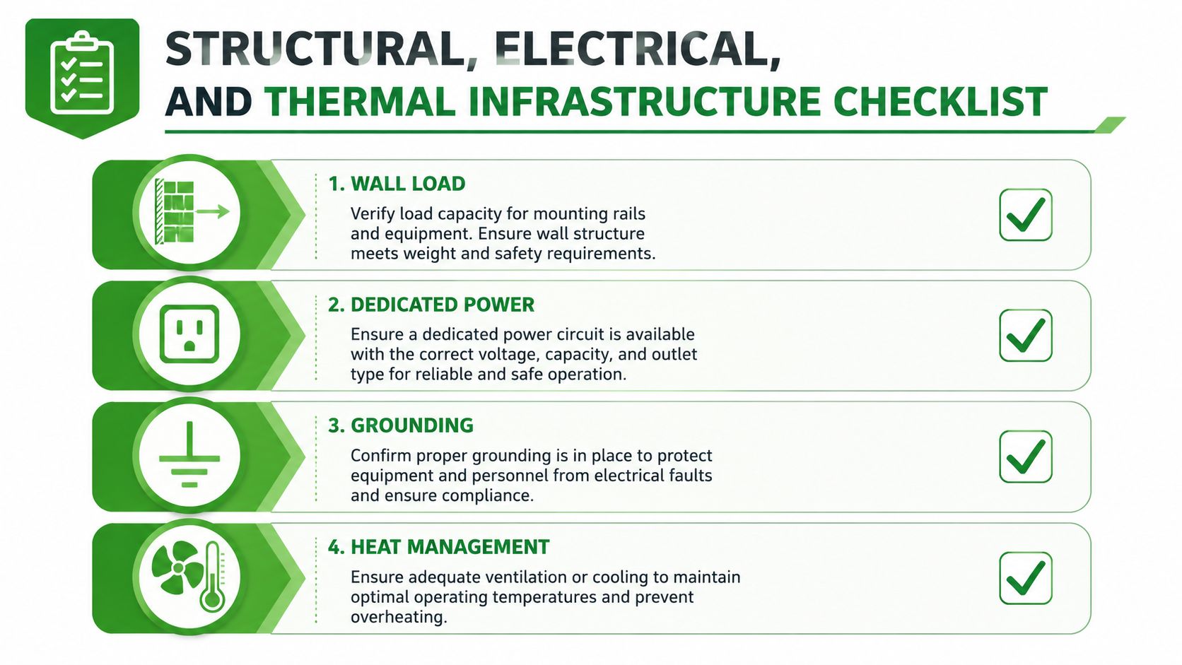
Infrastructure comes first; the display is the final layer added. I sequence the work in four passes: verify the structure, design the electrical system, confirm grounding and protection, then prove the thermal path.
Verify the structure before drilling
A drywall wall over wood studs, a CMU wall, and a steel-stud partition have different anchor capacities. Confirm the substrate, locate load-bearing members, and use a purpose-built rail or unistrut frame when the load must spread across several points. A freestanding frame can be safer than placing a heavy assembly on a weak architectural wall.
The support must stay rigid and flat. A small rail deviation can become a visible alignment problem across a large array. Use structural drawings, manufacturer mounting details, laser levels, and documented anchor installations instead of relying on visual judgment. Plan removable sections at this stage, because service access becomes difficult after finishes and furniture are in place.
Design power for operation and service
Dedicated circuits keep display loads separate from general receptacles that may already carry changing loads. Calculate the display's maximum specified demand, include processors and rack equipment, balance circuits across the panel, and retain practical capacity for startup and future service. If the existing distribution equipment cannot support the schedule, review commercial electrical panel upgrade services before finalizing the design.
Commercial specifications may call for 230 V AC at 50 Hz input and maximum power consumption at or below 350 W/m² in certain installations, with signal transmission over CAT or fiber under 100 meters (commercial video wall specifications in the GeM technical document). Treat those values as equipment-schedule requirements, not universal assumptions. Confirm the selected manufacturer's circuit, disconnect, and operating requirements before wiring.
Grounding and bonding deserve the same attention as branch-circuit sizing. Bond metal rails, racks, enclosures, and associated equipment according to the electrical design and inspection requirements. Add surge protection where the project calls for it, then identify circuits clearly at both the panel and the wall.
Keep heat from becoming a service problem
Indoor LED systems commonly operate around 200 to 400 W/m², while outdoor systems may require 5,000 to 10,000+ nits brightness and IP65 to IP68 protection because sunlight, dust, and moisture change thermal and environmental demands. Do not seal a display cavity until intake, exhaust, room HVAC, and maintenance access have been confirmed.
The exact clearance comes from the equipment and mounting design. The rear cavity, fans, power supplies, cable bends, and removable sections must be coordinated together. A clean face without a service path will cost more to maintain and can turn routine replacement into a wall-opening project.
Low-Voltage Cabling, Signal, and Control Systems
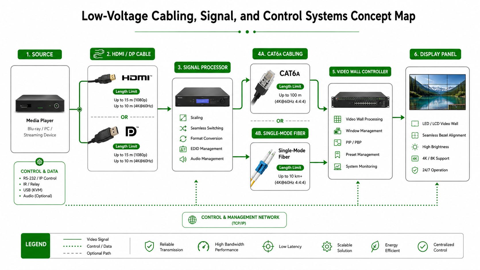
Signal reliability depends on topology. Start at the source and draw every handoff to the pixel. A typical path may include a media player, HDMI or DisplayPort connection, processor, distribution equipment, CAT or fiber transport, controller, receiver cards, and display modules.
Short copper connections can work well when the source and processor sit near the wall. Longer runs create more opportunities for attenuation, interference, poor bend radius, and difficult troubleshooting. For walls separated from the rack by a longer pathway, CAT6A, fiber, or an appropriate extender platform usually gives the design more flexibility than forcing a long direct HDMI run.
Build the pathway around the system
A 2×2 retail wall may need one source route, one processor location, power pathways, and a compact control connection. A 6×1 control-room array may need several source inputs, a controller with independent output mapping, operator control, and clearly labeled routes to each display position.
Use separate pathways for line voltage and low voltage where required by the electrical design. Label both ends of every cable, leave a documented service loop, maintain bend-radius requirements, and install spare pull strings in raceways. Put junction boxes and access points where a technician can reach them without removing finished millwork.
Signal transport can use CAT6A with suitable extenders, fiber links, or AV-over-IP encoders and decoders. The correct choice depends on distance, resolution, latency, network architecture, and the owner's operating model. A processor should also support the intended source switching, scheduling, monitoring, and fault recovery rather than just distributing an image.
The control layer may include RS-232, IR, IP control, Crestron equipment, or a dedicated video wall controller. Confirm who will operate the system and what happens after a power interruption. For installation practices covering pathway layout and termination, see commercial low-voltage cabling installation.
The Installation Process and What the Timeline Really Looks Like
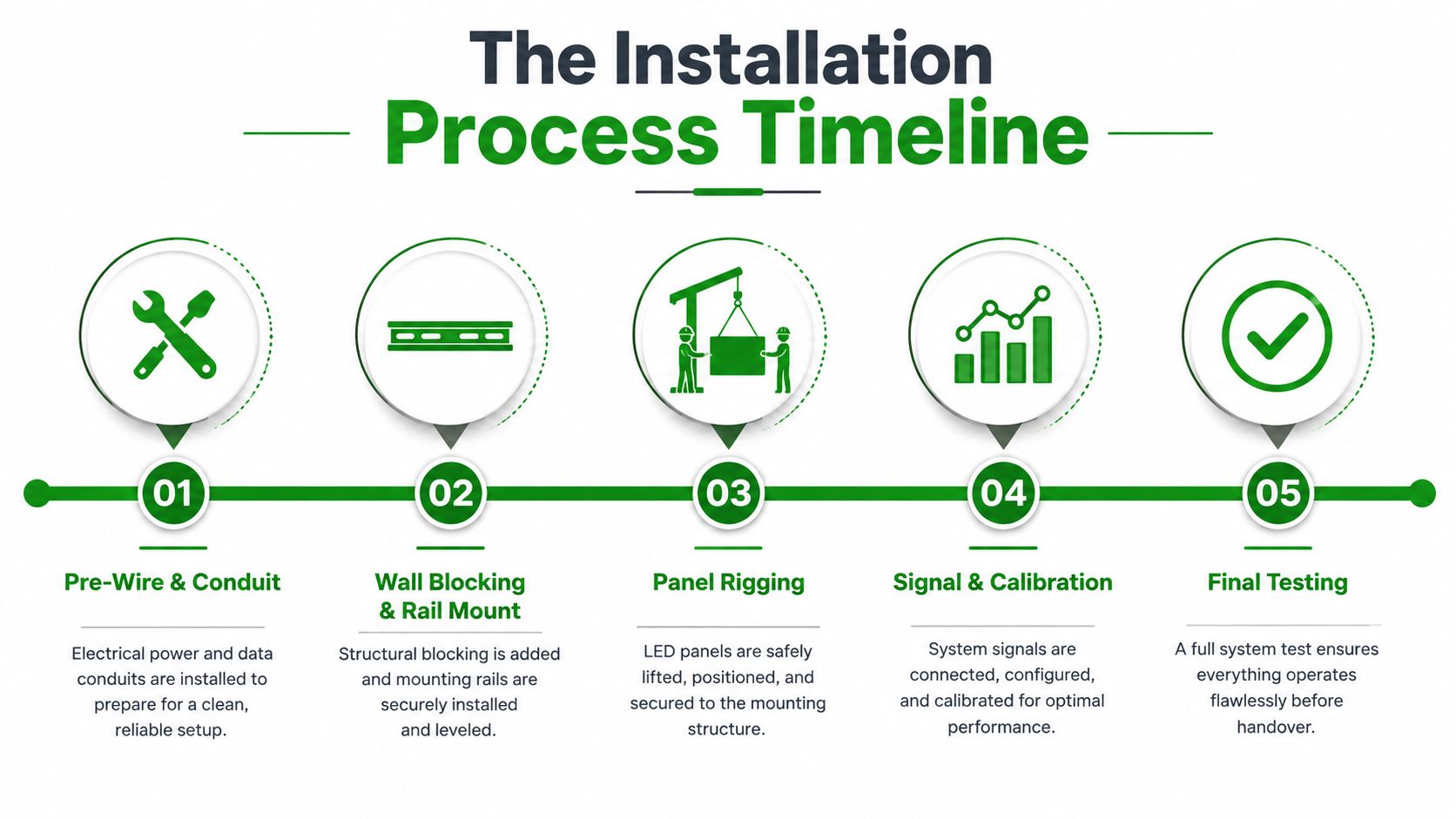
A video wall installation moves in a fixed physical order, even when the project schedule feels chaotic. Rough-in comes first. The crew installs conduit, boxes, cable pathways, blocking, and any required backing before the finish surface closes.
Once the wall is ready, the mounting rail or structural frame is installed and aligned. The crew checks anchor locations, plane, level, and service clearances before lifting cabinets or panels into position. Direct-view LED cabinets may require two technicians for safe handling, while larger or more complex assemblies can require dedicated rigging equipment and a controlled lift plan.
A typical field sequence
- Pre-wire and rough-in: Install circuits, conduit, boxes, grounding conductors, data pathways, and rack connections.
- Backing and rail installation: Verify blocking or structural support, then mount and level the rail or frame.
- Panel or cabinet placement: Rig the equipment, secure it to the structure, and protect finished surfaces.
- Cable termination: Dress power and signal cables, label both ends, and maintain service loops.
- Mechanical alignment: Adjust the array so seams, cabinet edges, and panel planes remain consistent.
- Configuration and calibration: Map inputs, load content, match brightness, calibrate color, and test control functions.
A straightforward 2×2 lobby wall can take 2 to 3 working days on site after rough-in, while a 6×1 control-room array can take 7 to 10 days including commissioning, according to the project assumptions provided for this guide. Those durations aren't promises. Freight delays, hidden structural conditions, union requirements, after-hours work, occupied spaces, and unready client content can all extend the schedule.
Alignment and commissioning need protected time
The final day shouldn't be the first time the content owner sees the wall. Give the AV team approved content, source devices, network credentials, control requirements, and operating instructions before commissioning. Mechanical alignment is easier before trim and signage conceal the access points.
The fastest installation isn't the one with the fewest people on site. It's the one that arrives with complete drawings, available circuits, verified support, delivered equipment, and a prepared commissioning checklist.
Testing, Commissioning, and Long-Term Maintenance
A wall isn't finished when every panel lights up. Sign-off should confirm that the system produces a consistent image, responds to control commands, recovers from faults, and remains serviceable without destructive removal.
Start with the display itself. Check module or panel alignment, dead pixels, brightness matching, color uniformity, viewing-angle consistency, and visible seams. Direct-view LED systems need calibration across the entire surface, not just a visual check at the center.
Commission the complete signal chain
Test every source and input combination. Verify resolution negotiation, EDID behavior, HDCP handshakes, processor mapping, control commands, and recovery after a source or display restart. If the wall supports failover, disconnect the primary path under controlled conditions and document what the operator sees.
The handover package should include:
- Circuit documentation: Identify breakers, disconnects, receptacles, and equipment served.
- Signal schedule: Record source names, processor inputs, outputs, cable labels, and destinations.
- Calibration record: Save brightness, color, configuration, and processor settings.
- Firmware record: Document versions and approved update procedures.
- Service map: Show front and rear access points, removable trim, spare modules, and rack locations.
- Test results: Record image checks, control tests, failover behavior, and client acceptance.
Lifecycle planning belongs in the original budget. Recent independent guidance indicates that annual maintenance under a service contract can add 2% to 4% of hardware cost, while reactive specialist repairs can cost more (video wall installation cost guidance from Current Cost). Another recent guide places installed costs in 2026 at roughly USD 600 to USD 1,500 per square foot or more, depending on complexity, and discusses service contracts and commissioning as buying criteria (Sostron's LED video wall cost guide).
Watch the warning signs
Color drift, uneven brightness, fan noise, intermittent signal drops, and unexplained resets deserve investigation. They can indicate failed terminations, cable fatigue, heat problems, power-supply issues, or configuration changes.
Cleaning, firmware review, calibration, and accessible panel replacement keep small defects from becoming an outage. The owner should know who performs those tasks, how quickly replacement parts can be obtained, and whether a technician can reach the affected component without dismantling the wall.
Why a Licensed Commercial Contractor Is the Smart Hire
A commercial video wall combines line-voltage power, low-voltage communications, structural mounting, rigging, and AV control. When those scopes are split among several companies without one accountable coordinator, a failed display can produce a chain of finger-pointing. The electrician blames the processor, the AV integrator blames the circuit, and the mounting crew points to the wall.
A licensed commercial contractor can coordinate the infrastructure under a defined scope, with clear drawings, inspection responsibility, documentation, and warranty boundaries. That doesn't eliminate the need for specialized AV design, but it gives the owner a practical point of accountability for the parts that meet at the wall.
Code and documentation matter
The electrical design should address applicable NEC grounding and bonding requirements, including Article 250, along with local amendments and inspection requirements. In California, the project may also involve Title 24 energy compliance, particularly where lighting controls, equipment power, or related building systems are part of the work. Wall-mounted structures may require seismic bracing and structural review based on the building and jurisdiction.
Unlicensed or poorly documented work can create inspection problems and may complicate manufacturer warranty claims. A proposal should identify the rack, mounts, conduit, circuits, grounding, low-voltage pathways, controls, calibration, testing, and maintenance responsibilities rather than hiding those items under “installation.”
For projects that need one team to manage the commercial electrical scope, commercial electrical contractor services can provide a starting point for evaluating the required qualifications. Access Electrical and Lighting operates as a California C-10 electrical contractor and lists low-voltage infrastructure, digital signage, video walls, copper and fiber cabling, electrical distribution, troubleshooting, and maintenance among its commercial capabilities.
The strongest proposal is the one that makes failure ownership clear. If the rack, conduit, power, mounting, signal pathways, calibration, and service access are coordinated from the beginning, the owner has an advantage when something needs correction years after the ribbon-cutting.
If you're planning a video wall for an office, retail center, hospitality space, or control room, ask Access Electrical and Lighting to review the site, panel capacity, grounding, pathways, mounting support, and service access before equipment is ordered. Visit Access Electrical and Lighting to discuss a coordinated commercial electrical and low-voltage installation plan.