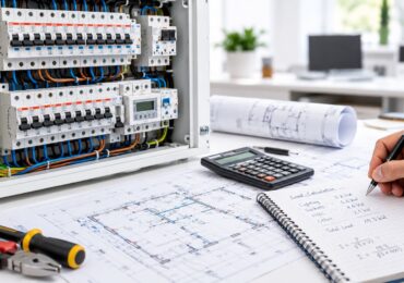
A tenant calls at 9:10 on a Monday morning because half the suite has gone dark. In a Costa Mesa medical office building, a patient area is without lighting, a workstation has dropped offline, and someone believes a relay or wall switch took the hit. A maintenance employee reaches for a replacement device in the closet, ready to make the outage disappear.
That response is understandable, but in commercial facilities it can create a larger problem. The failed device may be reacting to a loose termination, an overloaded shared circuit, heat damage in the panel, a failed control interface, or a downstream load that has been stressing the switching equipment. Good electrical switch repair identifies the reason the switch failed before anyone restores service.
Why Commercial Switch Repair Is More Than a Parts Swap
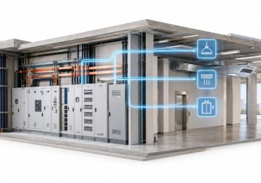
A residential light switch usually controls a relatively simple branch circuit. Commercial properties may involve 208, 240, or 480 volt systems, three-phase loads, switchgear assemblies, shared tenant circuits, motor controls, fire alarm interfaces, emergency lighting, and equipment that must remain coordinated with the building's distribution system. A device that looks like a standard switch may be part of a larger control or protection arrangement.
The first question isn't “Which replacement switch do we have?” It's “What changed, and what else is connected to this circuit?” A switch can fail because its contacts are worn, but it can also fail after repeated heating, vibration, contamination, loose conductors, or a problem upstream. The worldwide high-voltage equipment reliability survey found that major switching failures are measurable but relatively infrequent in well-maintained utility systems. That reliability makes an unexpected commercial failure worth investigating, not dismissing as a routine parts issue.
Map the circuit before replacing anything
A technician should identify the source panel, breaker or fused disconnect, affected loads, control wiring, and any equipment that shares the circuit. That map determines whether a like-for-like device replacement is appropriate or whether the switch is part of a larger distribution problem.
A careless swap can leave the original cause in place. A replacement device may be damaged again, a loose connection may continue heating, or a repair may affect fire alarm operation, emergency lighting, tenant equipment, or the coordination of protective devices.
Practical rule: Treat every unexplained switch failure as evidence. The failed component is a clue, not automatically the cause.
Separate a local fault from a system fault
Operational data supports that distinction. A datacenter switching study reviewed 4,681 switch failures over a three-month period, with hardware faults, software bugs, and unplanned power loss all represented among the causes. Nearly 50% of the failures lasted six minutes or less, while a smaller group lasted hours because isolation, removal, and replacement were required, as documented in the datacenter switching failure study.
Commercial teams should apply the same logic even when the device is a wall switch or disconnect. Before replacing it, determine whether the symptom points to contact failure, power quality, a damaged conductor, a load problem, or a broader switchgear condition. Facility managers who need help deciding who should perform the work can review this guidance on commercial electrical repairs in Southern California.
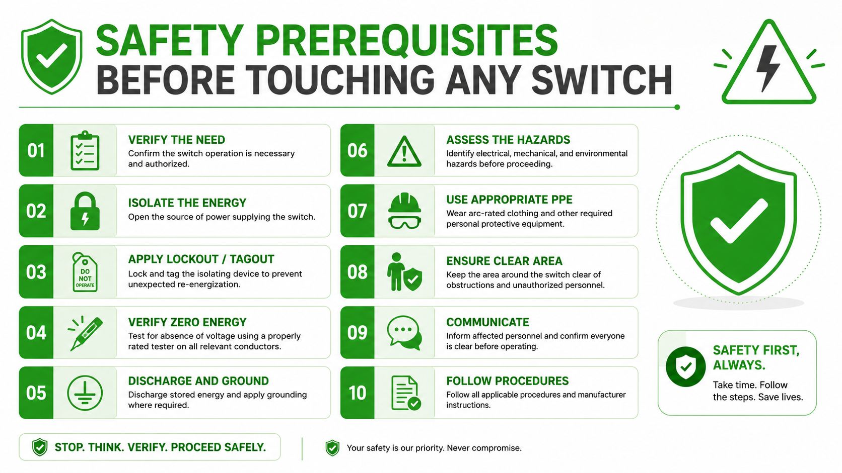
Safety Prerequisites Before Touching Any Switch
No diagnostic convenience justifies working on an unidentified energized circuit. Before touching a commercial switch, a qualified technician establishes the circuit boundary, controls the energy source, and proves that the conductors are de-energized.
Establish control before opening the enclosure
Start by identifying the upstream breaker, fused disconnect, or other source. Notify affected tenants and operations staff, post signage, and explain what equipment will lose power. The lockout/tagout procedure should identify the person controlling the lock, the equipment being isolated, the expected outage, and the conditions for re-energization.
After opening the disconnect or breaker, apply the lock and tag. Don't rely on a label alone. Verify that the correct circuit has been isolated, and account for other sources such as generator feeds, control transformers, backfeed through equipment, or multiple supplies in a switchgear assembly.
The safe switch repair procedure begins with de-energizing the circuit, removing the cover, verifying zero voltage, checking conductors, and testing continuity with the circuit off. That sequence is appropriate for basic device troubleshooting, but commercial work also requires attention to the system's energy sources and the technician's qualifications.
Prove zero voltage
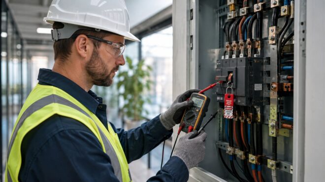
Use a properly rated tester for the equipment and environment. A qualified technician confirms the instrument on a known live source before testing, checks all relevant conductor-to-conductor and conductor-to-ground combinations, then confirms the instrument again on a known live source. A dead display by itself doesn't prove a dead circuit.
Wear voltage-rated insulated gloves appropriate to the task, arc-rated clothing where the panel's available incident energy requires it, and safety glasses. Remove conductive jewelry and keep tools controlled. Maintain the required working space in front of the equipment, including the 3-foot working depth and width requirements described by NEC 110.26(A), as applicable to the installation.
Before work starts, document the isolation steps and identify the qualified person performing the task. Confirm that no tenant, cleaner, operator, or maintenance worker can re-energize the circuit while the enclosure is open. California facility teams can also use this OSHA electrical safety standards resource when reviewing internal procedures.
Diagnostic Workflow for Identifying the Root Cause
After lockout/tagout and zero-voltage verification, begin with visible evidence, then move to electrical testing. The sequence matters. Replacing the device first can remove useful clues while leaving a heat-damaged termination or upstream fault in service. Treat the repair as a root-cause investigation, not a parts swap.
Start with what the device is showing
Inspect the faceplate, device body, terminals, conductors, and enclosure for discoloration, melted plastic, arcing pits, carbon tracks, oxidation, loose mounting screws, or heat migration. A warm or darkened conductor can indicate resistance at a termination rather than a failed switch alone. Check nearby insulation for brittleness, deformation, or heat that has traveled beyond the device.
With the circuit still isolated, operate the mechanism. A toggle that feels loose, binds, fails to hold its detent, or moves without a clean action may have an internal mechanical failure. Compare the switch poles and terminals with the wiring diagram and device rating. A replacement must match the voltage, current, pole configuration, switching duty, enclosure, and application.
Test continuity and terminations
Disconnect the switch as required, then set the multimeter to resistance or continuity mode. Toggle the device through each position and compare every pole with its expected open or closed state. A sound switch should show continuity only in the ON position, according to this field repair diagnostic method.
Inspect every termination for lost torque, back-stabbed conductors, damaged strands, poor wire preparation, and aluminum-to-copper combinations lacking an approved connection method. Review the upstream breaker, panel termination, bus connection, and downstream load. A switch that tests correctly in isolation can still be connected to a circuit with a failing breaker, compromised conductor, or abnormal load.
| Diagnostic Step | Test Performed | Likely Root Cause |
|---|---|---|
| Visual inspection | Examine terminals, insulation, enclosure, and device body for heat or arcing | Overheating, loose connection, contamination, or insulation damage |
| Mechanical check | Operate the handle or toggle and inspect mounting | Worn mechanism, broken internal parts, or poor enclosure support |
| Continuity test | Measure each pole while toggling the device with power isolated | Open contact, contact welding, or incorrect terminal identification |
| Termination inspection | Check conductor condition, connection method, and torque | Thermal cycling, loose termination, damaged conductor, or incompatible metals |
| Upstream and downstream review | Check breaker, bus connection, load behavior, and control interfaces | Overload, power disturbance, equipment fault, or broader distribution issue |
Record findings before reassembly. A useful report names the failure mode, not only the part number. “Switch replaced” provides little history. “Line terminal overheated, insulation affected, termination corrected, downstream load checked” gives the next technician a clear starting point. Facility teams that need help extending the investigation beyond the device can review electrical troubleshooting services. When testing reaches energized equipment, service changes, or work outside qualified in-house capability, stop and refer the task to a licensed C-10 contractor.
Common Failure Patterns Seen in the Field
Commercial switch failures often follow recognizable patterns, but the symptom only sets the direction of the investigation. In retail spaces, offices, and light industrial buildings, a parts swap can restore operation while leaving the condition that caused the failure in place.
A corridor lighting toggle that works intermittently may have a worn internal mechanism after years of frequent use. The handle feels soft, the lights respond inconsistently, and the device may fail when pressed at an angle. Replacing the switch can correct the immediate symptom, while inspection of the box and terminations helps determine whether heat, movement, or another condition contributed.
A warm faceplate accompanied by buzzing or discoloration points toward a connection problem. Oxidation can develop at line or load terminals, and repeated heating and cooling can loosen a termination. A breaker that resets normally does not make that connection safe. Resistance at the termination can keep generating heat while the device still appears to function.
Match the symptom to the likely mechanism
Common field patterns include:
- Intermittent receptacle-switch operation: A back-stabbed conductor or loose terminal may lose contact after thermal cycling. The repair may require re-terminating the conductor rather than installing another device.
- Three-way lighting failure: A stairwell light that operates from one location but not another can indicate a failed traveler connection, an incorrectly identified common terminal, or a worn three-way switch.
- GFCI nuisance trips: Repeated trips may result from downstream load imbalance, moisture, leakage, or a device problem. Resetting the GFCI without tracing the downstream circuit leaves the initiating condition unresolved.
- A breaker that trips and resets: The breaker may be responding to a fault, overload, heat-damaged connection, or failing load. Repeated resets can increase risk and conceal the original condition.
- Legacy mercury switch replacement: Older commercial interiors may contain mercury switching devices. Replacement requires identifying the device, handling it appropriately, and selecting a modern control suited to the circuit and application.
Use patterns as evidence, not conclusions
A buzzing device, warm cover, or intermittent light narrows the investigation. It does not justify a parts swap before the source is isolated and the circuit is tested. The operational failure review connects switching failures with hardware stress, power disturbances, and operating conditions, which matches field situations where the failed device is only one part of the event.
Repeated failure changes the repair decision. If a replacement switch develops the same symptoms, stop treating the device as the cause and examine the circuit, load, enclosure, and upstream equipment before further replacement work.
When to Call a Licensed C-10 Contractor
A dark tenant space may need only a failed switch, or it may point to a damaged connection upstream. In-house staff can report symptoms, identify affected occupants, operate equipment under an approved procedure, and perform limited maintenance allowed by the owner's safety program. The boundary changes when the work alters the electrical installation, requires a permit, exposes complex equipment, or involves energized commercial distribution. Those conditions belong with a qualified electrical contractor.
A like-for-like replacement can fit an organization's authorized maintenance scope, depending on the device, voltage, location, training, and company policy. A standalone control is a different risk from a switch inside a panel, disconnect, motor-control assembly, or multiwire branch circuit. If the technician cannot verify the circuit, device rating, and isolation point, the repair should stop and be escalated.
Escalate when the scope expands
Call a licensed California C-10 contractor when the work involves:
- Panelboards, switchgear, bus connections, feeders, or service equipment.
- A new circuit, circuit extension, altered branch-circuit configuration, or load calculation.
- Aluminum conductor remediation or questionable aluminum-to-copper terminations.
- Multiwire branch circuits where shared neutrals and simultaneous disconnect requirements matter.
- GFCI or AFCI additions, box-fill changes, or other work that may trigger permitting.
- Heat damage beyond the device, repeated nuisance tripping, fire alarm interfaces, or equipment controls.
- Any condition requiring an inspection, design review, coordination review, or a new single-line diagram.
A licensed C-10 contractor is also the practical choice when the failure cannot be isolated to the switch. Repeated device failures, damaged conductors, hot terminations, unexplained breaker operation, or a circuit serving critical equipment require broader testing and a repair plan, not another parts swap.
California licensing, apprenticeship, and contractor requirements are separate matters. Property teams should verify the contractor's active C-10 license, insurance, qualifications, and ability to coordinate with the local Authority Having Jurisdiction. The California Division of Apprenticeship Standards provides state information on apprenticeship and workforce matters. Confirm the contractor's license and the project scope separately.
| Task | In-House Maintenance | Licensed C-10 Contractor |
|---|---|---|
| Report symptoms and isolate an area under an approved procedure | Appropriate when staff are trained and authorized | Can provide emergency response and formal isolation support |
| Like-for-like low-voltage device replacement | Possible within company policy and qualifications | Appropriate when device type, access, or risk is uncertain |
| Continuity testing on a de-energized, verified circuit | Appropriate for qualified personnel | Preferred when readings indicate a broader fault |
| Panel, switchgear, feeder, or bus work | Not a reasonable general maintenance task | Proper scope for a licensed electrical contractor |
| New circuit, circuit extension, or load change | Escalate | Contractor evaluates design, code, permit, and inspection needs |
| Aluminum remediation or multiwire branch-circuit work | Escalate | Contractor determines approved repair and testing method |
| Permit, inspection, and compliance record | Provide site access and records | Prepare, coordinate, and close the permitted electrical work |
Delaying escalation can complicate an insurance claim, property sale, tenant dispute, or inspection. A low-cost repair becomes difficult to defend when the property has no record of who performed it, what was tested, or whether the altered installation met applicable requirements.
Documentation, Permits, and Compliance After the Repair
A commercial switch repair is unfinished when the lights come back on. The facility needs a record showing what failed, what changed, how the circuit was tested, and whether the installation was altered.
Begin with the repair report. Identify the asset or panel, affected area, date, technician or contractor, device details, observed failure mode, root cause, installed parts, test results, and restoration time. Add photographs when heat damage, arcing, corrosion, conductor damage, or enclosure deterioration affected the repair decision.
Match the permit question to the scope
California electrical work follows applicable building and electrical requirements, including Title 24 Part 3. Energy-related lighting and control work may also involve Title 24 Part 6, especially when lighting controls, retrofits, or related systems change. Permit requirements depend on the jurisdiction and exact scope. The owner or contractor should confirm them with the AHJ before work starts.
A like-for-like replacement may receive different treatment from work that changes infrastructure. New circuits, circuit extensions, box-fill changes, and GFCI or AFCI additions can require permits and inspections. A device that looks identical does not eliminate compliance questions if the wiring method, protection, box, circuit arrangement, or load has changed.
Keep these records in the property maintenance file:
- Test records: Continuity, voltage verification, functional checks, and load observations.
- Termination records: Torque values or torque verification for disturbed connections.
- Thermal documentation: Infrared images and written findings when a scan was performed.
- Circuit records: Updated panel schedules, equipment identifiers, and single-line diagrams when the circuit changed.
- Credential records: Contractor license information, insurance documentation, and inspection details.
The local AHJ may require rough-in access before concealment and a final inspection after completion. Coordinate tenant access, equipment shutdowns, and clear working space before the inspector arrives. A complete file protects the owner and contractor, helps future technicians understand the repair, and gives insurers or buyers evidence of responsible maintenance.
The OECD/NEA failure-analysis report on switching devices describes switching failures arising from design, manufacturing, internal components, overheating, and other conditions. Preserve the reasoning behind the repair, not only the receipt for a replacement device.
Prevention, Follow-Up, and Final Checklist
Prevention starts with the failure history. A facility that logs only the replacement part loses the information needed to spot recurring heat, vibration, contamination, loading, or termination problems. The asset record should make the next inspection more targeted than the last one.
Set inspection tasks according to the equipment and operating conditions. High-amperage disconnects may justify recurring infrared review, while panel terminations need scheduled torque verification by qualified personnel. After a seasonal load peak, inspect equipment that ran heavily or showed any temperature, noise, odor, or nuisance-trip symptoms. The exact interval should follow the manufacturer's instructions, the site risk profile, and the contractor's maintenance program rather than an arbitrary calendar.
Record the useful details
After each repair, enter:
- Failure mode: Open contact, welded contact, loose termination, heat damage, mechanical failure, or another confirmed condition.
- Root cause: Load issue, power disturbance, vibration, contamination, conductor problem, or device defect.
- Corrective work: Parts replaced, conductors re-terminated, enclosure repaired, or upstream issue addressed.
- Verification: Continuity, voltage, functional operation, load response, and thermal findings where applicable.
- Responsibility: Technician or contractor identity, qualifications, license information when applicable, and completion date.
- Next action: The next inspection, follow-up test, or escalation condition.
Escalate immediately when the same circuit trips repeatedly, heat damage is visible, the switch is part of a panel or switchgear assembly, or the repair touches anything beyond the device itself. The JRC bulletin on power failures identifies switching and isolating apparatus among recurring contributors to primary power supply failures, reinforcing why a local symptom can deserve a distribution-level review. That power-failure bulletin is useful context when setting priorities for critical facilities.
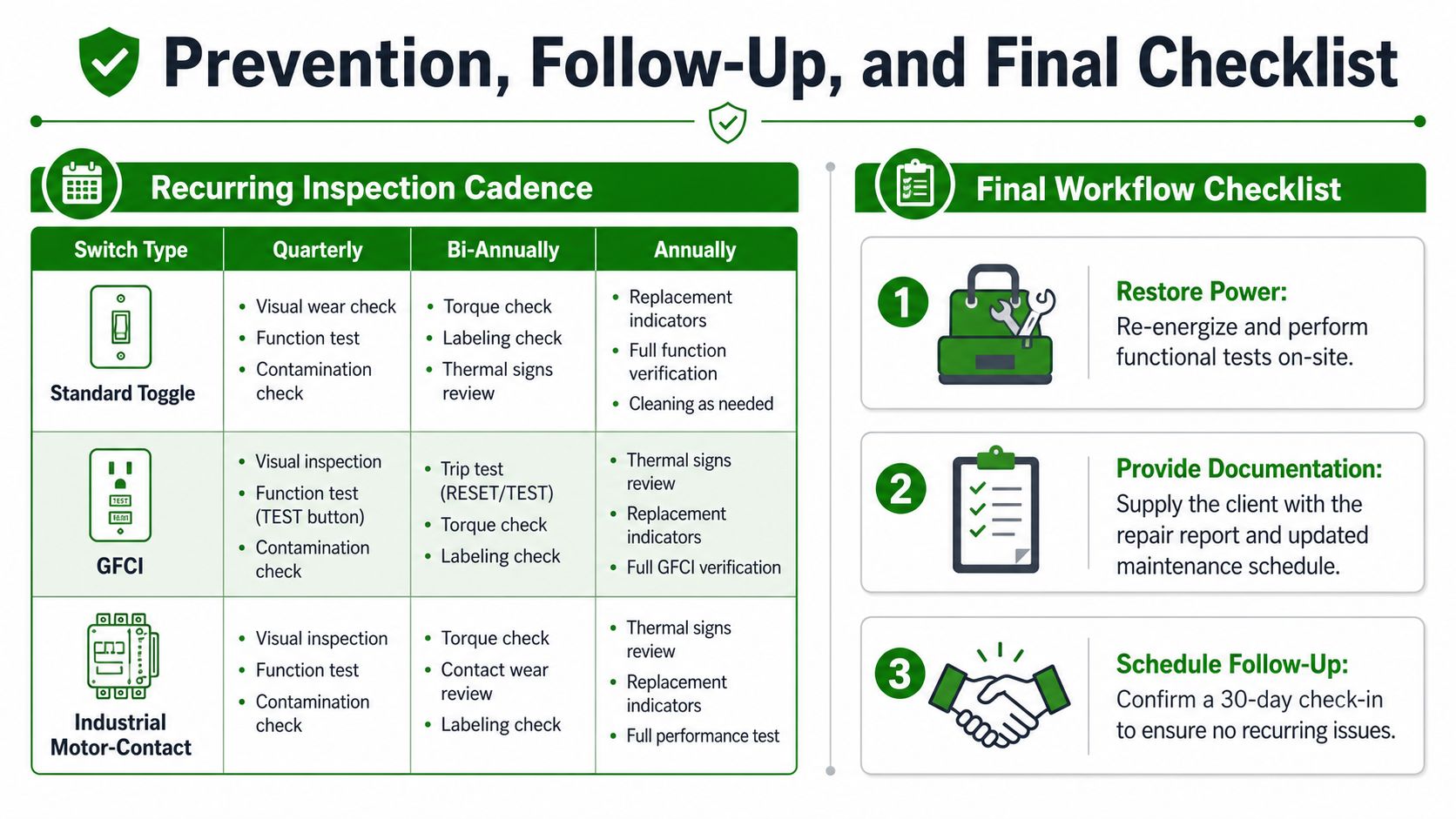
Run this checklist after every repair
- Safety: Confirm the circuit was isolated, zero voltage was verified, covers were secured, and the work area is safe.
- Diagnosis: Confirm the failure mode and root cause were recorded, not just the replacement part.
- Testing: Perform the required continuity, functional, load, and thermal checks.
- Escalation: Confirm no panel, feeder, circuit, load, or code issue remains unresolved.
- Documentation: File the report, photographs, test records, torque information, and updated circuit records.
- Follow-up: Assign the next inspection and identify the conditions that require a C-10 contractor.
Access Electrical and Lighting provides commercial electrical troubleshooting, switchgear and panel repair, infrared inspections, lighting maintenance, and Title 24 documentation for Orange County properties. If a failed switch may involve heat damage, distribution equipment, or a recurring outage, visit Access Electrical and Lighting to request an assessment and establish the right repair and follow-up plan.