A retail manager reports that one audio zone drops out whenever the store gets busy. In the same remodel, a digital sign flickers and a sensor network begins sending intermittent alarms. The first instinct is often to blame the amplifier, display, controller, or software. A closer inspection frequently leads to a much smaller part, the connector joining the cable to the system.
That connector isn't just a cap, plug, or clamp. It's the point where electrical continuity, mechanical support, environmental protection, and future serviceability meet. A connector can fit the cable and still be wrong for the voltage class, conductor material, current demand, data signal, sealing requirement, or installation environment.
The commercial market also makes the decision less simple than the phrase low voltage cable connector suggests. Connectors for data, power, coaxial video, outdoor cabling, marine systems, and low-voltage DC installations belong to different application families. Choosing by appearance alone is like selecting a vehicle part because it has the right color. It may look compatible until the system is loaded, exposed to moisture, or opened for maintenance.
Introduction Why the Right Connector Matters More Than You Think
A property manager usually notices the symptom, not the termination. The speakers go silent in one area, the video wall shows a brief interruption, or a building sensor stops reporting. A junior technician may see that every cable is physically connected and assume the installation is sound. That assumption can send the troubleshooting team toward amplifiers, network switches, control panels, or software before anyone checks the connector.
The connector deserves attention because it carries the system's practical burden. It must hold conductors firmly, keep contact resistance stable, resist movement, and suit the surrounding environment. A termination that works during commissioning can still become a service problem if it experiences repeated heating and cooling, vibration, oxidation, moisture, or cable pull.
Field rule: A connector isn't proven because the equipment powers up. It's proven when the termination remains reliable under the conditions the system will actually experience.
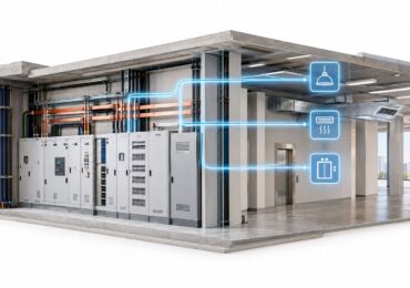
Commercial properties create especially difficult combinations. A tenant improvement might include distributed audio, digital signage, access control, occupancy sensors, lighting controls, and networked equipment in the same ceiling or pathway. Those systems may all use cables that a non-specialist calls low voltage, but their connector requirements can be very different.
This guide starts with the basic function of a connector, then separates the major connector families. It explains how to select a part by application risk rather than convenience, how to install and test it, and how to plan for blended audio, signage, and sensor networks. The objective is practical: help a property manager ask better questions and help a junior technician avoid a termination that looks acceptable but fails later.
Understanding Low Voltage Cable Connectors and How They Work
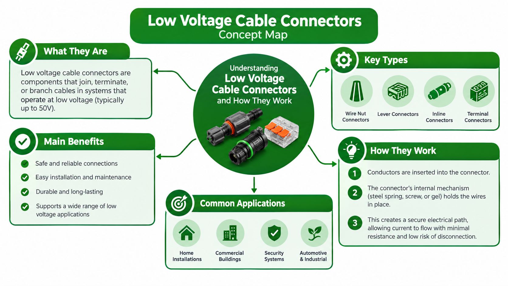
Think of a connector as a handshake between two cables. A good handshake has enough pressure to stay connected, enough contact area to carry the intended signal or current, and enough protection to remain dependable after the people involved move around. A cable connector performs the same job with conductors, shields, contacts, insulation, and a housing.
In commercial work, “low voltage” describes a broad group of systems rather than one universal connector specification. The cable may carry power, analog audio, digital data, control signals, or video. The conductor may be copper or aluminum, and the installation may be inside a conditioned room, above a ceiling, outdoors, underground, or in a location exposed to repeated handling.
The international framework behind household and similar copper-conductor connecting devices is IEC 60998. The International Electrotechnical Commission describes its scope as connecting devices for copper conductors in household and similar applications at rated voltages up to 1,000 V AC at frequencies up to 1,000 Hz and 1,500 V DC, with the first edition published on April 30, 1990, covering conductor sizes from 0.5 mm² to 35 mm². A technical revision published in 2002 replaced that first edition, marking the progression from a broad framework to a more mature connector standard, as documented by the IEC 60998 publication record.
Start with the conductor and the job
Before selecting a part, identify four basics:
- What the cable carries: Power and data connectors aren't interchangeable merely because both operate below a line-voltage threshold.
- What the conductor is made of: Copper and aluminum require compatible contact surfaces and termination methods.
- What the cable size is: The connector must accept the actual conductor range, not just a similar-looking cable.
- Where the connection sits: An indoor rack connection has different exposure than a buried or weather-facing splice.
For a practical overview of cable pathways and termination planning, review this guide to low-voltage cabling installation. The central idea is simple: the connector is part of the system design, not an afterthought added after the cable has already been pulled.
Main Types of Low Voltage Connectors Explained
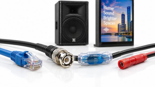
The most common mistake is treating every low-voltage connector as a general-purpose joining device. An RJ45 plug belongs to a data system. A BNC connector belongs to a coaxial system. A gel-filled splice belongs to an environment where moisture protection matters. A connector can be excellent in its intended role and unsuitable everywhere else.
| Connector Type | Best For | Environment | Key Consideration |
|---|---|---|---|
| RJ45 | Ethernet data, networked controls, and some audiovisual links | Indoor cabinets, equipment rooms, and protected pathways | Maintain pair arrangement, termination quality, and cable category compatibility |
| BNC | Coaxial video and radio-frequency applications | Equipment racks and protected audiovisual pathways | Preserve shielding and impedance characteristics |
| Splice and butt connector | Inline joins for compatible power or control conductors | Enclosures or accessible protected locations | Match conductor material, size, insulation, and termination method |
| Gel-filled connector | Moisture-exposed low-voltage splices | Outdoor, damp, or landscape-adjacent locations | Confirm the product is rated for the cable combination and exposure |
| Insulation-piercing connector | Approved tap connections where the design permits piercing | Specialized distribution and service applications | Follow the applicable standard and manufacturer instructions, especially for sealing and conductor size |
Data connectors are not power splices
An RJ45 connector organizes twisted pairs so a network signal can travel with controlled relationships between conductors. It isn't a substitute for a connector designed to carry power or protect a splice from water. A BNC connector similarly preserves the geometry and shielding of coaxial cable, which is why forcing a different connector style onto a coax run can create signal problems even when the connection feels tight.
Power and control splices require a different review. The installer must consider conductor size, current, insulation, contact pressure, strain relief, and enclosure or sealing requirements. A small connector that physically accepts the wires may still lack the tested performance needed for the load.
Sealed connectors solve an environmental problem
Gel-filled connectors and sealed splice products protect the contact area from moisture and contamination. That doesn't mean every gel-filled product is suitable for burial, direct exposure, mixed conductors, or every cable construction. Read the product rating, accepted conductor range, installation orientation, and service instructions.
Blue wire nuts and similar twist-on products also require careful sizing. Use the blue wire nut capacity guide as a sizing reference, but verify the connector's own listing and application limits before using it in a commercial installation.
Standards are becoming more specialized
The connector category is fragmenting because the applications are becoming more specialized. IEC/IEEE 80005-3:2025 addresses low-voltage shore connection systems for marine power, IEC 63171:2025 addresses single-pair data connectors with current-carrying capability, and NEMA's 2025 plan includes ANSI C119.6 for non-sealed multiport connector systems rated 600 V or less for aluminum and copper conductors, as summarized in the standards overview for emerging connector families. The practical lesson is to identify the application first, then the connector family.
How to Choose the Right Connector for Commercial Installs
A connector selection meeting should begin with the system, not the parts bin. Ask what the connection carries, how much electrical or signal stress it sees, what materials it joins, where it will live, and whether a technician must open it later. Those answers narrow the field more effectively than color, price, or a familiar brand.
Use a decision filter
Voltage and current come first. A low-voltage label doesn't remove the need to verify rated voltage, current capacity, conductor range, and the system's duty cycle. If the connector creates excessive localized resistance, the termination can heat under load even though the equipment initially operates.
Copper and aluminum need deliberate compatibility checks. The contact method, surface treatment, compound requirements, and tightening procedure may differ. Never assume a connector rated for copper automatically suits aluminum, or that a connector designed for one conductor combination can be repurposed for another.
The environment changes the part. Indoor equipment racks may need accessibility and shielding. Outdoor or damp locations need sealing and resistance to environmental exposure. Pathways with vibration, repeated service, or cable movement need strain relief and mechanical support.
Compression and mechanical connectors also involve a trade-off. A compression connector depends on the correct tool, die, preparation, and compression sequence. A mechanical connector depends on the correct conductor seating and tightening procedure. In either case, the important question is whether the connector has passed the required performance tests, not whether the installer can make it feel tight.
| Installation condition | Selection direction | Main risk to control |
|---|---|---|
| Indoor data run | Use the connector family specified for the cable and network | Signal loss, pair disruption, or poor shielding |
| Indoor power or control splice | Use a listed connector matched to conductor and load | Loose contact or localized heating |
| Outdoor or damp power connection | Use a connector with appropriate environmental protection | Moisture ingress and corrosion |
| Permanent concealed connection | Choose a tested, documented termination method | Difficult diagnosis and inaccessible repair |
| Reconfigurable equipment connection | Favor accessible, serviceable interfaces | Future changes damaging the cable |
| Mixed copper and aluminum conductors | Confirm explicit material compatibility | Oxidation, poor contact, or unsafe heating |
Judge performance, not just fit
Industry specifications commonly require compression and mechanical connector types to meet Class A performance criteria under IEC 61238-1 or an equivalent standard. Those criteria involve type testing for electrical continuity, heating, and durability, not merely cable-size fit. The Ausgrid connector specification illustrates why this distinction matters in commercial electrical work.
For a 600 V-class low-voltage system, relevant validation may include ANSI C119.5 for insulation-piercing connectors or IEC 61238-1 and EN 50393 for cable joints and terminations. These tests address failure modes such as poor contact pressure, oxidation, and thermal cycling, as described in this connector testing reference.
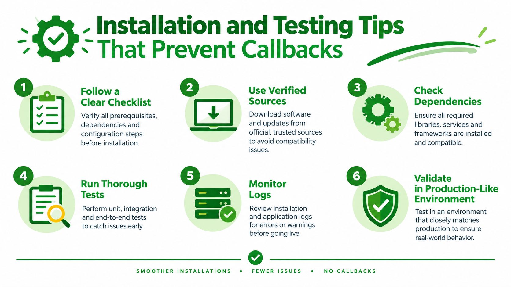
Installation and Testing Tips That Prevent Callbacks
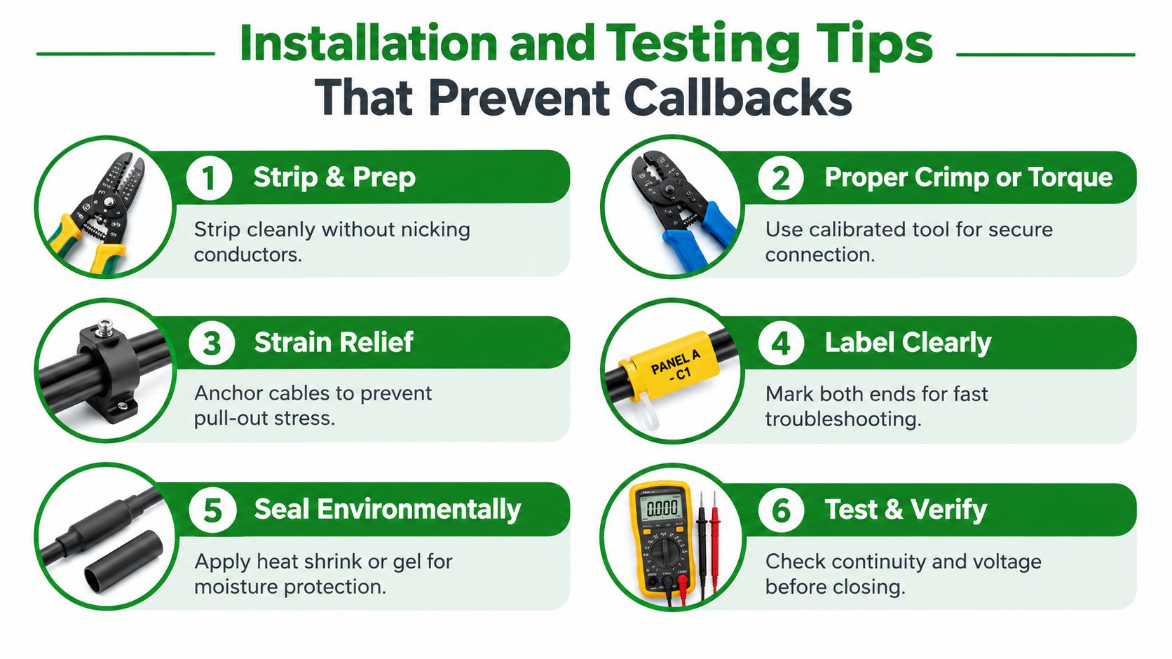
A reliable connector installation is a process that another technician can inspect, test, understand, and service. The physical assembly matters, but so do preparation, routing, labeling, environmental protection, and records. A connector hidden above a ceiling without a label can become a recurring labor cost even if it was installed correctly.
Prepare the conductor cleanly
Strip only the insulation needed by the connector instructions. Nicked strands reduce the quality of the termination, while excessive exposed conductor can undermine insulation spacing or sealing. Keep conductors clean, align them correctly, and avoid bending them sharply where they enter the connector.
Use the specified crimp tool, die, torque tool, or tightening sequence. A hand-tight mechanical connection can look complete while failing to develop the intended contact pressure. Conversely, excessive tightening can damage the conductor or connector body.
Relieve movement before it reaches the contact
A connector shouldn't carry the weight of a hanging cable or absorb repeated pulling from equipment maintenance. Secure the cable near the termination, provide strain relief where the product requires it, and leave enough service slack for normal access without creating a loop that can be snagged.
Label both ends of the run and identify the connected device, panel, zone, or pathway. In a retail ceiling, a clear label can turn an uncertain outage into a short, targeted service task. Good low-voltage cable management also separates power, data, and control pathways according to the project requirements.
Test before the ceiling closes
Testing should match the system and the connector's role. A technician may check continuity, polarity, pair arrangement, shielding, or signal performance for data and audiovisual systems. Power-related work may call for voltage checks, insulation resistance testing, or additional verification specified by the equipment and project requirements.
A visual inspection remains useful. Look for incomplete insertion, exposed conductor, damaged insulation, loose hardware, missing seals, unsupported cable, or a connector installed outside its approved orientation. Where appropriate, thermal inspection under operating conditions can help identify an abnormal hot spot, but it should be performed by qualified personnel using the correct equipment and safety procedures.
Document the closeout: Record connector type, cable identification, test result, location, and any manufacturer-specific installation requirement. The next technician should not have to guess what is above the ceiling.
Work in occupied commercial spaces adds another layer of control. Coordinate shutdowns, protect customers and staff below high-reach work, secure ladders and lifts, and restore ceiling tiles or finishes without burying access points. For critical systems, preserve the test record with the panel schedule, device list, photographs, and marked-up drawings.
Matching Connectors to Audio Signage and Sensor Networks
A commercial low-voltage scope often blends three different connection problems in one pathway. Distributed audio needs dependable conductors and, in some designs, shielding. Digital signage and video walls need signal integrity, cable management, and service access. Sensor networks need stable data or control connections, and some devices also need power at the endpoint.
Distributed audio
Audio terminations should match the cable construction and equipment interface. A connector that leaves a shield floating, reverses polarity, or loosens at a speaker can create noise, dropouts, or an entire silent zone. The technician should identify the amplifier output, speaker wiring method, zone topology, and access requirements before choosing an inline splice or terminal connection.
Keep audio connections accessible where practical, especially in tenant spaces that may be reconfigured. Label zones at the rack and at field devices so a manager can identify whether the fault affects one speaker, one branch, or the complete output.
Digital signage and video walls
Signage systems combine displays, media players, control hardware, and sometimes separate power connections. A BNC termination may suit a coaxial video path, while an RJ45 connection may serve network or control traffic. Neither should be treated as a universal substitute for the other.
The connector must preserve the cable's intended signal characteristics and remain serviceable behind the display. Provide a controlled path for bend radius, strain relief, and equipment movement. A display that must be removed for service shouldn't pull against a concealed connector or force a technician to disconnect unrelated power and data wiring.
Sensor and control networks
Sensors may be small, but their connectors face real reliability demands. A loose control termination can create a false occupancy reading, interrupt a building automation point, or make a lighting scene behave unpredictably. Verify the device pinout, conductor type, power requirement, communication protocol, shielding needs, and environmental rating.
The standards question should be answered at the system boundary. A connector intended for single-pair data with current-carrying capability belongs to a specialized data application. A sealed power connector belongs to a power and environmental application. A marine shore connection has a distinct standard family. Mixing these categories because the plugs appear similar can compromise reliability and compliance.
For property managers planning future additions, reserve pathway capacity, document spare cables, and use consistent labels. Access Electrical and Lighting provides commercial low-voltage installation, testing, maintenance, and repair for copper and fiber cabling as part of broader electrical and low-voltage scopes. A unified contractor can coordinate the connection details with the line-voltage work, ceiling access, controls, and closeout documentation.
Final Takeaways for Reliable Low Voltage Connections
A low voltage cable connector is a small component with system-level consequences. The phrase covers specialized families for data, video, power, control, moisture exposure, and emerging applications. Selecting the wrong family can create intermittent operation, difficult troubleshooting, signal problems, overheating, or premature replacement.
Low voltage also doesn't automatically mean low consequence. A German DKE roadmap reports that testing found almost 100% of samples ignited at low currents such as 1.3 A in DC, compared with about 60% ignition incidence for AC at 1.3 A, and it concludes that low-voltage DC installation technology can present substantially higher fire risk than AC, as documented in the German low-voltage DC standardization roadmap. Treat DC, outdoor, and high-duty-cycle connections as engineered terminations, not casual splices.
Before approving an installation, confirm that the connector:
- Matches the system's voltage, current, conductor material, and cable size.
- Belongs to the correct power, data, video, or control family.
- Has the required sealing, strain relief, and environmental rating.
- Uses the manufacturer's specified crimp, torque, or preparation method.
- Has been tested, labeled, photographed, and documented for future service.
For an existing property, start with the recurring symptoms. Map the affected zone, inspect accessible terminations, verify the connector application, and arrange qualified testing before closing walls or ceilings. For a planned remodel, involve the electrical and low-voltage contractor early so pathways, power, data, controls, and service access are coordinated.
Access Electrical and Lighting installs, tests, maintains, and repairs commercial low-voltage infrastructure for audio, digital signage, controls, copper, and fiber systems. Visit Access Electrical and Lighting to discuss connector selection, troubleshooting, testing documentation, and coordinated electrical and low-voltage work for your next commercial project.